Wire Routing

Pitot Tube, AOA Tubes, Reconnect overhead Panel Wire

April 29th,2014, 3 hours

I routed the Pitot tube and two AOA tubes from the pilot side wall to underneath the dash and to their respective locations. Connected the AOA tubes to the AOA BOX and the Pitot Tube to the GSU25’s.

The overhead panel contains switches for controlling the WingTip Taxi and WingTip Landing lights, the Nav lights, the marker lights and the strobe lights. These overhead switches have LED lights in them. When you push in the Marker Light switch the LED and Marker LIght switch LED should light up. They did not. I found I had routed the power wire back to the fuse panel instead of the VPX J10-4. Corrected the wire placement and LED’s work now when the Marker Light (Nav Lights) are switched on.

Avionics DYNON D10A

Dynon D10A, MAGINT – MAGINC

April 24 2014, 1 hour

I took a break from the normal building process to play with the gadgets. I decided to partially setup the Dynon-10A. I set up the MAGINT (47290) (Intensity – Total Field) and the MAGINC (+58.5) (Inclinantion). These settings are from the NOAA website.

SETTING MAGNETIC INCLINATION ANGLE AND INTENSITY (REQUIRED) To calibrate your EFIS-D10A heading, you must input your location’s current magnetic inclination angle and intensity. Before doing this, you must obtain these two values for the geographic location where you will be performing the calibration.

From Dynon’s website link:
IMPORTANT: The two values needed from the following page are INCLINATION and TOTAL FIELD. Horizontal Intensity is NOT used.

20140430-071406.jpg

20140430-071417.jpg

20140430-071353.jpg

Fuselage

Elevator, Flaps, Trim settings

April 19th, 2014 8 hours

I started the day with setting up the VPX with the flaps setting. As of now I decided to use the following flap settings. Vfe speeds are only suggested speeds at this point and will be changing.

Flap. Actual. Delta. Vfe
Setting. Degree. Degrees Speeds
(0) -3
(10) 7 10, 118 knots
(20). 17 10, 95 knots
(35) 32 15, 87 knots

I set up the VPX with the above position setting. I do not have enough resolution between -3 to 0 degree to have the flaps use the “trail” as the first position. I decided this was not an issue and so looked at the delta between the degree changes and made the flaps setting match a 0, 10, 20, 35 flap setting. I will test this further in the flight testing envelope to verify this is a good setup.

I then moved to setting up the aileron trim in the G3X, simple procedure.

Next was the Rudder trim setting. This was enabled in the G3X, again an easy setup.

Finally the Elevator trim was addressed. I had been afraid to work with this one knowing it would likely invoke changing the control push rod setting throughout the system. I was correct, lots of work on this. It turns out the GSA28 pitch servo stops where acting as the stop for the up position. I opened the access tunnel cover just below the rear passenger seat to adjust the push rod going to the back of the airplane. I then noticed the down position was being stopped by the elevator idle arm hitting the forward wall in this location as well. I shortened the rod by turning the eye bolt in. This moved the elevator idle arm out ward and thus helped correct the inference issue occurring with the GSA28 servo. I then adjusted the push rod connecting the GSA28 servo to the elevator control bell crank to allow the servo arm to be more centered in the 110 degree over center bracket. I then verified the travel on for the elevator and noted it to be 29 and 24 degrees. The GSA28 has no interference now with the travel of the elevator. I had to enlarge the gap on the side tunnel walls where the stick control rods connect to the center pass thru aileron connection forward of the rod. The copilot side was hitting in this area and now no longer is an issue.

I added fasteners to the under elevator trim plates. Torqued the Rudder attachment bolts and the rudder eye bolt nut where it screws into the rudder attach point.

Engine

Air Inlet Engine Intake, RPM sensors, Alternator Field Wire

April 28th, 2014. 3 hours

I started the evening by putting in place the inlet air intake for the engine. This was the first time I installed the air inlet since the AC compressor and Alternator belts had been tightened. Sadly I had to modify the pilot side air inlet since the back side contacted the ac compressor. More epoxy and fiber. On the copilot side air inlet I added a reflective two ply aluminum foil to protect it from the close proximity of the #2 exhaust pipe. I am not sure how the foil will work but I am hoping the “Sticky Stuff” and epoxy around the outer edges will hold the foil in place. Time will tell. I plan to use this same stuff on the engine cowling near the exhaust pipe and mufflers. This is left ver radiant barrier used in our roof. I did a flame test and it passed.

I moved to connecting the Alternator Field Wire to the J12-7 pin on the VPX Pro to control the alternator field. Quick and easy.

I then worked with the two ECU RPM wires. The G3X will accept 2 RPM inputs and will only display the highest RPM of the two. I changed the two connectors coming from the two ECU’s and connected an extension cable routing it over the the GEA24. I then connected it to Pin 6 and 8 on the J243 connection.

Engine

CHT, EGT, other various items

April 20, 2014, 10 hours

I terminated the CHT and EGT sensor wires to the sensors installed on the engine using the supplied fasteners for the loop terminals and the shield wire coverings. I decided to shrink wrap each connection point since it appeared to me that after some time inflight the protective shielding wire covers were likely going to allow the terminals to contact the various surrounding metal surfaces outside the covering.

After the EGT and CHT wire had been terminated I cleaned up the install by routing all the wires and securing them to the spark plug wire runs thus cleaning up the install.

I worked with the fuel bypass line passing through the upper air baffling above cylinder #5 and slipped a round plastic grommet around and through the baffling. I then used red RTV to help seal the hole.

Brooklyn decide to come help daddy build today……her first day on the job… and you can guess who was in total control of the situation. 🙂

I connected the left front air vent using the Stein eyeball vent, using the supplied scat tubing.

20140430-074123.jpg

20140430-074132.jpg

Engine

Engine control cables, brackets

April 25th, 2014, 12 hours

I focused on the throttle, mixture and prop control brackets. Most of the time was spent figuring out how I wanted to route the cables and where the brackets needed to be placed. Of the three cables supplied by Vans only one was long enough for use on the Prop gov control. This was the 72.5″ version. I returned the other shorter cables to Vans and purchased the 60″ and 67″ versions.

The prop gov was to use a longer control arm but with the required direction of motion and lack of room because of the AC Compressor the travel on quadrant will be limited. It will travel about 2/3 the distance it should when cycling the prop. The prop gov itself can fully cycle the full rotational distance as required. I drilled the attach point of the cable to the quadrant lower than originally designed for. This allowed for greater travel on the prop control knob in the quadrant.

Engine

More Engine Adel Clamp action

April 19th, 2014. 20 Hours

My Dad and I continued working on the engine area with more Adel clamps being added to the mix. My dad started to focus on the bottom cylinder shroud and baffle rods. These are made from stainless steel and had to be cut, bent and threaded to accept the retaining nuts. Not a fun job but my dad got it done. Took him most the day to work on those rods.

I started working on the cabin tunnel and various items needing to be finalized. I mounted the TWC Battery to the inside of the firewall. I then focussed on the heater hose routing through the tunnel. I added two clamps to hold the scat tubing to the left and right tunnel wall as to route the tube away from the control rods of the rudder pedals. I then focused on routing it through the area where the fuel valve was. I originaly was to reduce the scat tube to a 3/4″ tube and then convert back to the standard size but decided against it since the scat tube can be reformed easly through the narrow space by the fuel valve. I added a cushion below the tube on the front spar to keep the tube from wearing a hole in it.

At the end of the day we had decided to mount the prop once again and tighten the AC compressor and Alternator. We did this with mininal issues but will need to retighten the Alternator belt prior to first flight.

20140421-075636.jpg

20140421-075642.jpg

20140421-075648.jpg

20140421-075654.jpg

Engine

AC Compressor Hose, Engine wire Adel Clamps

April 18th, 2014. 16 Hours

My parents came in for the Easter weekend so my dad and I started cleaning up some of the wire routing around the engine. Various Adel clamps were placed to hold the spark plug wires and various other sensor wires around. I continued to work on the engine air intake tubes by adding three nut plates to the pilot side intake to snorkel tube. I decided since we had just changed the AC system in my truck and had all the vacuum equipment that we should draw a vacuum on the AC system in the plane. SO I crawled into the tail section of the airplane and finalized all the wire by zip tying them into place along with adding the transponder cable and antenna. Used my dads help to fasten the antenna since I needed two people to tighten it. Attached the inlet and outlet hose for the condensor and we filled the dryer up with about 2 oz of oil since we could not get all the oil into the compressor that we wanted in the AC system. I then attached the inlet and outlet hose to the dryer. I cromped the two hoses to the compressor. My dad then drew a vacuum on the system. Last we checked the system was still holding good vacuum after we disconnected the vacuum pump.

Engine

Routing of engine sensors, spark plug wires, AC hose

April 13th, 2014, 18 hours

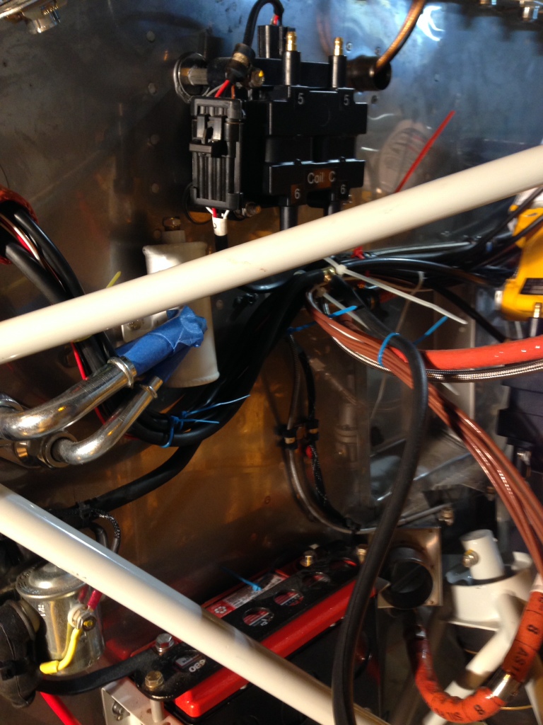
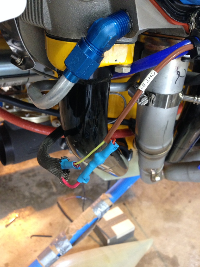
Started routing the thermocouple wires for EGT and CHT wires along wi the fuel flow sensor. Routed the spark plug wires and added tie wraps to the locations where I want to use ADEL clamps.

I worked on various engine baffles in the front of the engine. Added the rubber baffle material to the two side front baffles and the two baffles over the front of the engine.

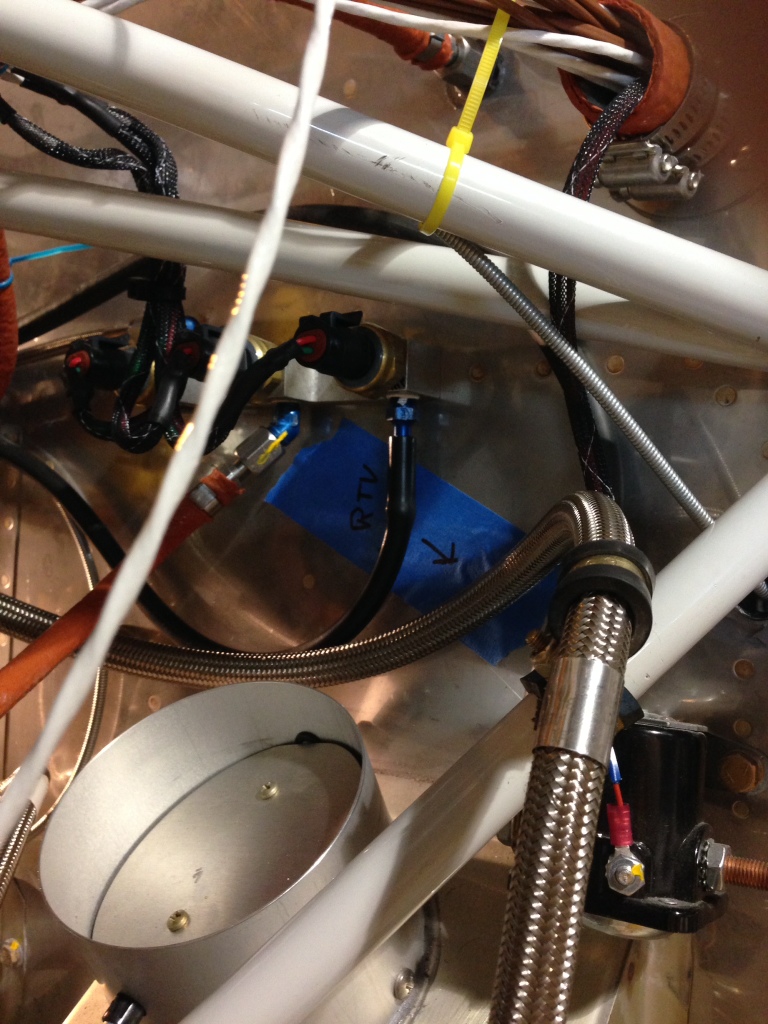
Routed the air conditioner large and small hose from the firewall to the compressor. I had to punch holes in the copilot side rear engine baffle to allow the hoses to pass thru. I also punched a hole for the EFII crank timing sensors to pass thru. Ultimately these holes will be sealed with red RTV once all the hoses and wires are ADEL clamped in place.

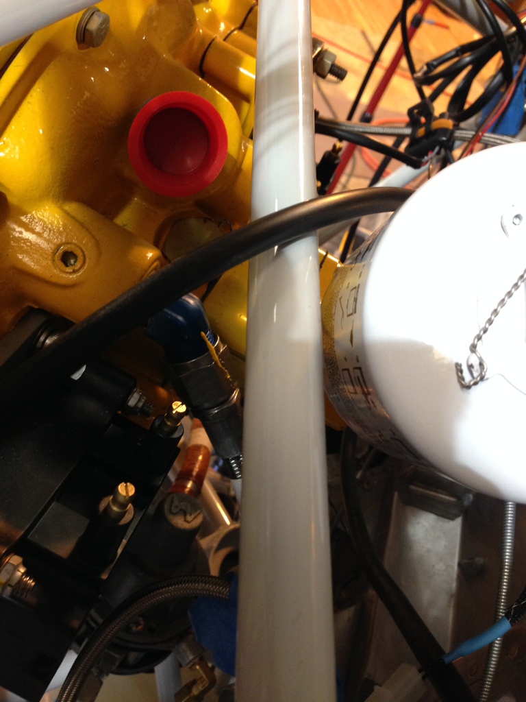
Routed the manifold pressure hose from number 5 cylinder to the EFII dual MP gauges and add a “T” and routed the off shoot to the G3X MP sensor mounted on the firewall.

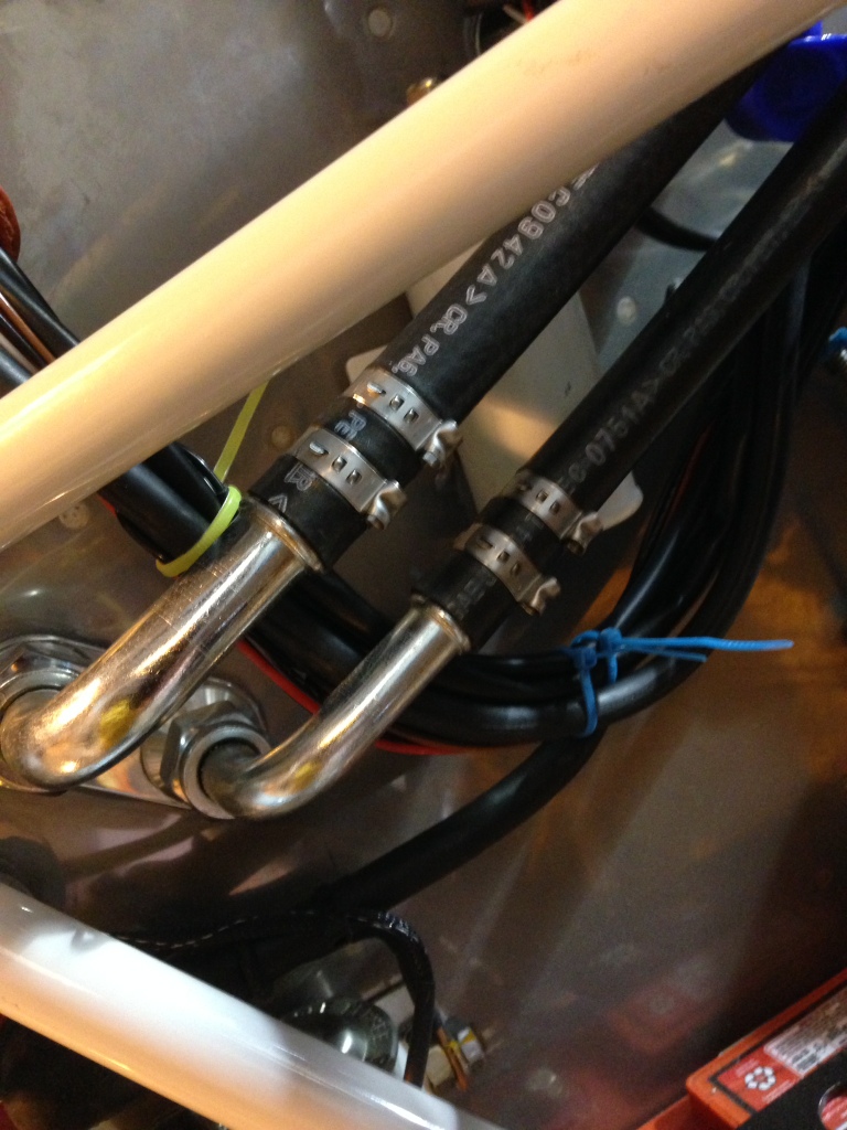
I ordered engine fuel hoses from TS Flightline all fire sleeved.
1) Mechanical fuel pump to fuel servo
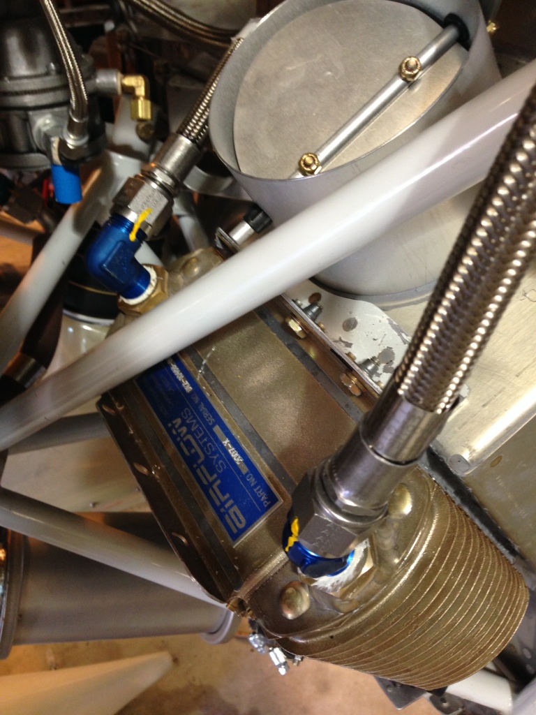
2) fuel servo output to the red cube, R12204C5.5, -4 str/90′ f/s
3) red cube to purge valve input, R12204C16F, -4 str/90′ f/s
4) red cube output to firewall, R12204A46F, str/str f/s
5) firewall to left side fuel tank “t”, R12204A50, -6 str/str
6) mechanical fuel pump to fuel pressure gauge, R12204A12F, str/str

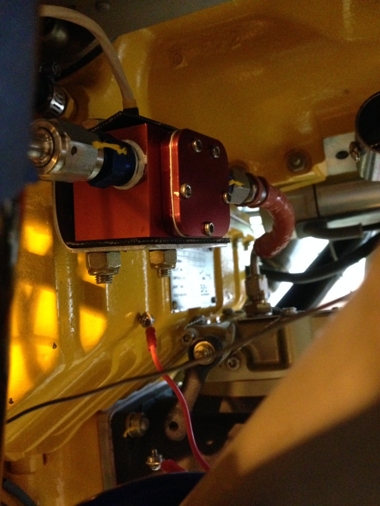
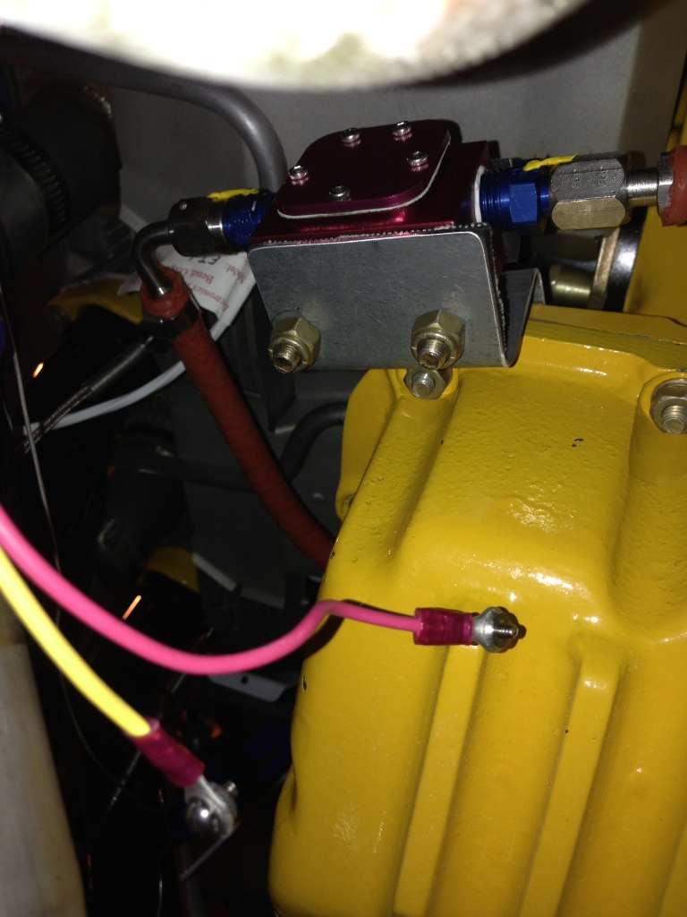
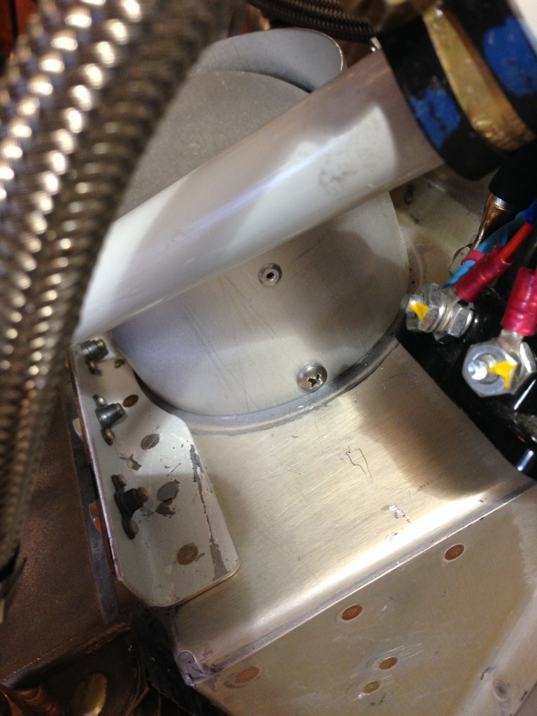
Fabricated a red cube mount bracket. I wanted to let the red cube be supported by the hose but it seemed to floppy to me so I made a bracket. I mounted the red cube to the bracket using rubber so that it might be cushioned more so than if it was directly mounted to the bracket. I used aluminum and am sure it will crack advetualy but I will be watching for it.

20140416-105033.jpg

20140416-105045.jpg

20140416-105055.jpg

20140416-105102.jpg

20140416-105039.jpg

Engine

Misc Engine items completed

April 9th, 2014. 3 hours

Worked a couple of misc items on the engine. Final fitted the oil cooler lines just after I filled the oil cooler with oil. Sadly did not capture the amount of oil the oil cooler contained… Maybe 3/4 a quart. Fastened and torqued the oil line on e cooler and back on the engine.

Drilled two screw holes into the oil cooler air flow valve and inserted two screw to hold it in place.

I am getting ever so close to finalizing the inlet air scoop for the engine. Cut then Fiberglas and repeat.

20140416-102608.jpg

20140416-102658.jpg

20140416-102710.jpg