Building the Fuselage
Category Archives: Fuselage
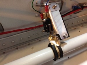
Section 39, Control System
Elevator Travel
June 26, 2014 – 10:03
2 hours, 25 June 2014
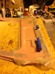
I spent more time looking at the elevator control rod system. There is a slight interference when the stick is full aft. I adjusted the threaded rod end by one revolution and then torqued and torqued sealed the nuts back in place on the rod end through bolt and rod end jam nut. I then went to the elevator and added a small piece of McMaster Carr door seal strip to the bump stop and glued in place with the elevator in full up position. This limited the travel by one more degree making the final up position be at 29 degrees deflection.
Elevator Control Tube and Aileron cross link between sticks
June 25, 2014 – 10:21
3 hours, 24 June 2014
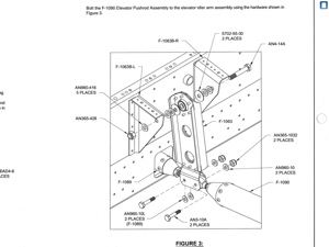
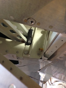
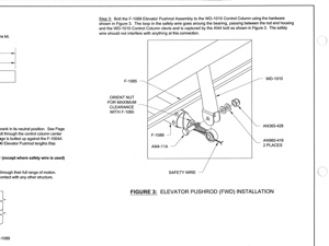
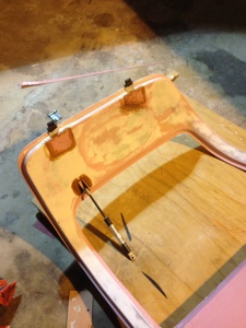
I spent time with tearing apart the center tunnel section to gain access to the elevator push tube where it connects to the control sticks. This area is very tight and there is interference between the elevator tube and the aileron cross control rod when in full stick aft. I had to lengthen the distance between the tube end and the attachment point so the aileron Control rod would not hit the jam nut on the face of the tube. This requires the threaded rod end to be extremely far out of the end of the tube thus requiring a safety wire to be put in place. I made the adjustments and safety wired the rod end per Vans Section 39-4.
The quest for a control stick solution
June 25, 2014 – 09:49
6 hours, 21 June 2014
This day Dave Forster and I went on a whirlwind chase to compare the RV10 control stick to Phil Perry and Nick Nasfinger. This took us to two different airports across Houston so Dave offered up his Rocket for the pursuit. We launched out of Polly Ranch for our first stop at DUNHAM and private airfield on the north east side of Houston. We grabbed Phils control sticks and looked over his project and discussed a couple of items. We then launched out to see Nick’s RV10 at Pearland. I sat in his RV10 and was able to get an idea of how a flying RV10 feels. We then launched back over to Polly Ranch.
We essential decided to make a bend in the stick just below where the vertical portion holding the infinity grip attaches to the curved portion. This allowed us to clear the panel switches with out any issues. Thanks Dave to the help on this one!!
We still think we have a seat issue with the new seat sitting a little taller than stock and this is making the stick movement become a little less since you have taken away the clearance under the stick. I will be looking into this more as we get closer to first flight. I will likely add rudder pedal extensions so I can move the seat back further to guarantee the stick movement.
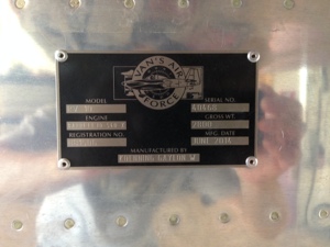
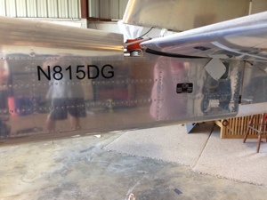
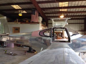
N number, data plate, experimental sticker
June 19, 2014 – 14:25
1 hours, 18 June 2014
I applied the EXPERIMENTAL stickers to the insides of the doors. Attached the identification plate to the fuselage. Applied the N- number to the fuselage.
Starting to put close out panels on
June 10, 2014 – 07:53
2 Hours, 8 June 2014
I have started to attach the panels that wont be removed during the inspection. Although I wonder if they will be asked to be removed as my pinion is there is only wire behind the panel and nothing to look at otherwise they should stay on. We shall see….
Fuel Tank Sender Calibration
May 25, 2014 – 22:58
May 25, 2014. 8 hours
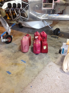
Today I went to Pearland Regional to get 40 gals of fuel to calibrate the fuel tanks. The G3X system makes this process very easy and straight forward. I decided to poor in 1 gal at a time which gave me great resolution. Although 1 gal at a time is a long drawn out process, I want good measurements.
I filled the left tank first and reached the tab at 22 gal. The sender unit stopped registering at 25 gals but the tank easily fit 30 gal. Stumped the tank, no contamination yet. I then disconnected the line from the mechanical fuel pump and turned on then electrical fuel boost pump and flowed several gal of fuel through it.
Flow Rate (left/right):
1 gal at 1 minute 16 seconds.
I did the same process to the right side with the same results.
I then pulled the purge valve control to the ICO position with the throttle at 1/2 and mixture fuel rich. Dave Forster my neighbor stopped by and lent some help with verifying fuel purge valve lines where flowing fuel. We then verified what the flow rate was I with the main fuel line from the mechanical fuel pump to the servo. This gave me a flow rate of 1 gal at 1 minute 14 seconds. We then pushed the tail all the way down to the ground, almost a 14 degree pitch ( I think I remembered that pitch correctly.). Again we pumped 1 minute 18 seconds, the pump inlet never un ported with only 2 gallon the tank.

Interior Painting
May 25, 2014 – 22:38
May 24, 2014. 8 hours
Spent the day repainting the interior overhead console since I inadvertently used the wrong paint the night before. Oh what joy that process was. After lots of sanding I was able to complete my task and applied new paint to the over head console and the cabin top adjacent areas.
I also worked on making the lower cover panel for the right door. Lots of fiberglass work and covering of the hinge access locations.
Interior and Door work
May 23, 2014 – 13:41
May 18, 2014. 8 hours
The horrible fiberglass work continues…. I have been working on the left door trying to finish it before I install the window. I had smoothed out the inside door the best I could with UV Smooth Prime and then a Dupli-Color primer filler (FP101 Grey Filler). This actually worked well as I didn’t expect it to. I then followed it with Dupli-Color Acrylic Enamel Gloss White (DA1670) and then a Dupli-Color Acrylic Enamel (Crystal Clear Coat DA1692).
Prior to all the painting I closed out the hinge attach points. We plan to cover the lower panel that covers the access into the door mechanism with some material yet to be picked out.
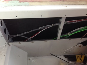
Close out panels and AOA switch
May 7, 2014 – 13:35
April 30, 2014 3 hours
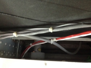
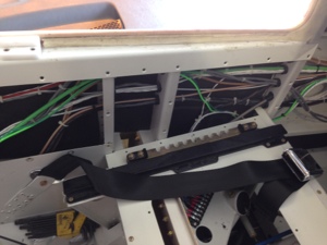
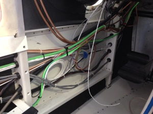
I decided it would be best to start closing up the panels in the back of the airplane along with securing the wires being routed in these areas. I also installed the AOA switch to the flap sensor so when the flaps transition out of the -3 degree setting the AOA is alerted to the configuration change.
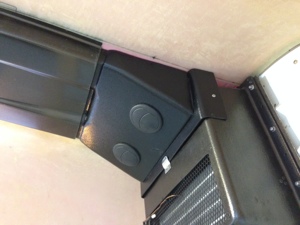
I also installed the transition from the evaporator tot he AeroSport overhead. I drilled a couple of holes and added some rubber door seals. I also installed the close out over head panels to the overhead. It looks good but sadly I scratched the overhead when I was working with the AeroSport Headliner inserts.
Elevator, Flaps, Trim settings
April 29, 2014 – 10:05
April 19th, 2014 8 hours
I started the day with setting up the VPX with the flaps setting. As of now I decided to use the following flap settings. Vfe speeds are only suggested speeds at this point and will be changing.
Flap. Actual. Delta. Vfe
Setting. Degree. Degrees Speeds
(0) -3
(10) 7 10, 118 knots
(20). 17 10, 95 knots
(35) 32 15, 87 knots
I set up the VPX with the above position setting. I do not have enough resolution between -3 to 0 degree to have the flaps use the “trail” as the first position. I decided this was not an issue and so looked at the delta between the degree changes and made the flaps setting match a 0, 10, 20, 35 flap setting. I will test this further in the flight testing envelope to verify this is a good setup.
I then moved to setting up the aileron trim in the G3X, simple procedure.
Next was the Rudder trim setting. This was enabled in the G3X, again an easy setup.
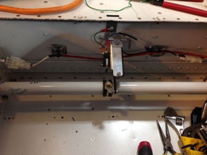
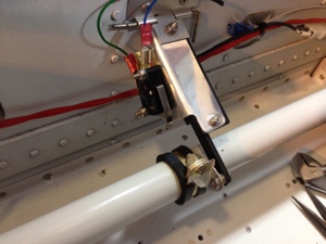
Finally the Elevator trim was addressed. I had been afraid to work with this one knowing it would likely invoke changing the control push rod setting throughout the system. I was correct, lots of work on this. It turns out the GSA28 pitch servo stops where acting as the stop for the up position. I opened the access tunnel cover just below the rear passenger seat to adjust the push rod going to the back of the airplane. I then noticed the down position was being stopped by the elevator idle arm hitting the forward wall in this location as well. I shortened the rod by turning the eye bolt in. This moved the elevator idle arm out ward and thus helped correct the inference issue occurring with the GSA28 servo. I then adjusted the push rod connecting the GSA28 servo to the elevator control bell crank to allow the servo arm to be more centered in the 110 degree over center bracket. I then verified the travel on for the elevator and noted it to be 29 and 24 degrees. The GSA28 has no interference now with the travel of the elevator. I had to enlarge the gap on the side tunnel walls where the stick control rods connect to the center pass thru aileron connection forward of the rod. The copilot side was hitting in this area and now no longer is an issue.
I added fasteners to the under elevator trim plates. Torqued the Rudder attachment bolts and the rudder eye bolt nut where it screws into the rudder attach point.