Category Archives: Avionics

Panel Design

Front Panel Express Main Panel arrived

2.5 hours, 25 June 2014

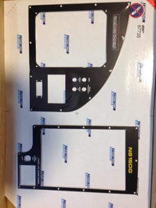
After spending many hours converting the CAD file I had for the original left side panel into Front Panel Express I received the final product in the mail yesterday. I must say overall there were only 2 issues that I saw once installing the panel. The lower right hole for mounting the AOA screen was not all the way through drilled. The IGN/ECU switch panel bezel was larger than I thought I had measured and thus is “runs” over or “covers” a small portion of the horizontal line denoting ECU 1 and ECU 2 form the IGN switches plus the word “LIGHTING” is slightly covered on the bottom side of the bezel. Overall I see no issues with this.

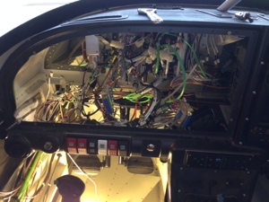
I pulled out all the items out of the panel and swapped over the back plates holding in the G3X screens to the new panel. This required match drilling and counter sinking for the rivet. I installed the new panel with only one issue as I dropped a very small nut that holds one of the rheostats in place for dimmer control. I could not find the nut and suspect it fell all the way down to the sub floor. No good… now I need to find a replacement. Plus I dont have a clue where that one went to and I made it a point during the entire build to ALWAYS find the items that “got away”.

Ops check good!

20140626-093652.jpg

Avionics

Updated Database in G3X system and GTN-750

1 hour, 24 June 2014

I brought up to date all the databases in the G3X system and GTN-750. I had to first register the GTN750 system and G3X system. Uploads went well but did take a while a you have to load each G3X screen individually.

I also tried to update the G3X system software to 8.70. I am having some small difficulties but am talking with the G3Xperts. I am sure it will get resolved easily as I have already been given advise on what to try.

Avionics

FAR 91.413 and FAR 43-Appendix F. FAR 91.411 and FAR 43-Appendix E

2 hours, 20 June 2014

Von’s Avionics from Pearland came over to perform the transponder and Altimeter System Static testing. FAR 91.413 and FAR 43-Appendix F. FAR 91.411 and FAR 43-Appendix E. all systems passed without issue. The Dynon required some calibration tweaking of the offset. It was reading within 10 feet from -1000 to 25,000. The Garmin unites were spot on from -1000 to 25,000.

Inspected on 06/19/2014. Will be due in 2 years.

Avionics G3X Components Wire Routing

Re-routing of HID and Wing Tip Tax/Landing Light wire

4 hours, 6 June 2014.

I had performed an EMI test using the G3X previously and when the left HID and/or Wing Tip Taxi light was switched ON the EMI value went to 340% over. When the wings were wired I had not chosen the avionics system yet and hadn’t planned on routing the magnetometer in the left wing, things changed and so I need to change the wiring to accommodate the very sensitive magnetometer. I ordered 50 feet of 18 ga. shielded, twisted wire and pulled the old wire out and pulled in the new wire. According to the Garmin manual the cable shield should be terminated on both ends. I finished connecting the power, ground and shield wires and powered up the system. I only had a 4% rise in EMI. It passed.

Avionics

New Front Avionic Panels for middle and copilot side

2 hours, 6 June
I received the copilot and center avionics panels I ordered from Front Panel express. They turned out fantastic. I installed them and they fit very nicely.

I now need to create the pilot side panel.

20140609-104914.jpg

Avionics

Pushed airplane out of the hangar for first time

2 hours, 23 May 2014

I cleaned out the hangar a bit so I could move out the airplane as to maybe align the magnometer and perform some other checks. As it turns out I was not able to align the magnometer nor was I able to pass the EMI testing with the left HID and/or Taxi Light on. If only the right side was turned on it was ok but with the left on it drove the reading to over 300% more than acceptable. I do recognize I locally grounded the HID and Taxi light but with running a dedicated ground back for either the HID or Taxi light does not correct the issue. I am not sure of the solution yet but I think I might need the LED lights sooner than I thought.

20140602-134454.jpg

G3X Components Section 37, Fuel System

Fuel Tank Sender Calibration

May 25, 2014. 8 hours

Today I went to Pearland Regional to get 40 gals of fuel to calibrate the fuel tanks. The G3X system makes this process very easy and straight forward. I decided to poor in 1 gal at a time which gave me great resolution. Although 1 gal at a time is a long drawn out process, I want good measurements.
I filled the left tank first and reached the tab at 22 gal. The sender unit stopped registering at 25 gals but the tank easily fit 30 gal. Stumped the tank, no contamination yet. I then disconnected the line from the mechanical fuel pump and turned on then electrical fuel boost pump and flowed several gal of fuel through it.

Flow Rate (left/right):
1 gal at 1 minute 16 seconds.

I did the same process to the right side with the same results.

I then pulled the purge valve control to the ICO position with the throttle at 1/2 and mixture fuel rich. Dave Forster my neighbor stopped by and lent some help with verifying fuel purge valve lines where flowing fuel. We then verified what the flow rate was I with the main fuel line from the mechanical fuel pump to the servo. This gave me a flow rate of 1 gal at 1 minute 14 seconds. We then pushed the tail all the way down to the ground, almost a 14 degree pitch ( I think I remembered that pitch correctly.). Again we pumped 1 minute 18 seconds, the pump inlet never un ported with only 2 gallon the tank.

20140525-225748.jpg

20140525-225758.jpg

Wire Routing

Pitot Tube, AOA Tubes, Reconnect overhead Panel Wire

April 29th,2014, 3 hours

I routed the Pitot tube and two AOA tubes from the pilot side wall to underneath the dash and to their respective locations. Connected the AOA tubes to the AOA BOX and the Pitot Tube to the GSU25’s.

The overhead panel contains switches for controlling the WingTip Taxi and WingTip Landing lights, the Nav lights, the marker lights and the strobe lights. These overhead switches have LED lights in them. When you push in the Marker Light switch the LED and Marker LIght switch LED should light up. They did not. I found I had routed the power wire back to the fuse panel instead of the VPX J10-4. Corrected the wire placement and LED’s work now when the Marker Light (Nav Lights) are switched on.

Avionics DYNON D10A

Dynon D10A, MAGINT – MAGINC

April 24 2014, 1 hour

I took a break from the normal building process to play with the gadgets. I decided to partially setup the Dynon-10A. I set up the MAGINT (47290) (Intensity – Total Field) and the MAGINC (+58.5) (Inclinantion). These settings are from the NOAA website.

SETTING MAGNETIC INCLINATION ANGLE AND INTENSITY (REQUIRED) To calibrate your EFIS-D10A heading, you must input your location’s current magnetic inclination angle and intensity. Before doing this, you must obtain these two values for the geographic location where you will be performing the calibration.

From Dynon’s website link:
IMPORTANT: The two values needed from the following page are INCLINATION and TOTAL FIELD. Horizontal Intensity is NOT used.

20140430-071406.jpg

20140430-071417.jpg

20140430-071353.jpg

Avionics Wire Routing

Tunnel Battery and Center Arm Rest Audio connections

Jan 17-18th, 2013. 16 Hours

I terminated the center arm rest audio panel phone/mic connections along with the USB power point and 12V power point connections. I then moved to the center tunnel battery. Ran a 4 AWG ground wire from the battery to the firewall common grounding point.

20140120-093312.jpg

20140120-093318.jpg

20140120-093324.jpg

20140120-093330.jpg

20140120-093335.jpg

20140120-093346.jpg

20140120-093406.jpg