Category Archives: Avionics

Avionics Wire Routing

Wing Root wire connections

Jan 11th, 2013. 16 hours
I worked the wing root wire connections on both wings and both sides of the fuselage. I also routed wires as required from the wing into the fuselage and back out as needed. This was a long process. Also terminated the coax VHF antenna’s for a male connection at the fuselage and terminated both end of the vhf cable in the wing. I decided to split the Roll servo harness at the wing root, this allowed me to route the wire through the wing and connect the servo. I needed to do this since I could not properly operate the Garmin system since it requires the CAN buss to communicate with all devices on the buss unless you have a terminator for the buss. I figured it would be easier to add the root connection than to worry about the CAN buss termination point. This also allowed me to roll the wing very near the fuselage and connect the roll servo so I could properly power the Garmin system and upgrade the system software.

I did not add a connector for the Dynon or Garmin magnetometer at this point.

20140120-083907.jpg

20140120-083927.jpg

20140120-083934.jpg

Avionics

Avionics partial Power ON

Jan 7th, 2014, 3 hours.

I walked out to the hangar with my laptop in hand and thought to myself this was very similar to the 787 where as the laptop (MX Laptop) is a very integral part of the aircraft. Thinking to myself that I have to load software to the RV10 for it to know who it is was all to similar to the 787!

I worked on getting power turned on and a partial system check out today. I flipped the Master Contractor (Batt1) and the VPX came to life along with the G3X MFD. The VPX has a basic configuration from the factory with everything turned off by the connected MFD. I did have the laptop plugged into the VPX Pro so I could upload the VPX Planner configuration that would make the system match my actual wiring. This went as expected and worked very well.

I had most all the avionics boxes unplugged for initial power on and I will slowly add boxes. I did end up with the PFD and MFD connected so that I could get the larger display screen for the VPX items on the MFD. The AOA, CO, O2 systems had power. For some reason the O2 system would shut itself off if I didn’t tell it to turn on with in 5 seconds of initial power on. I will read the manual again and see what I am missing.

The dimmable lighting of the switches was operational also. A testing of all the switches connected to the VPX was accomplished without issues.

20140108-075307.jpg

20140108-075314.jpg

Avionics Wire Routing

Avionics wire work

Jan 4-5, 2014. 16 hours.

I terminated control wires to the starter and contractor coils on the firewall. I connected the starter sense wire with a 1k ohm 1 watt resistor back to the VPX Pro box so it can sense when the starter is engaged. I cut to length and terminated many of the wing root connections on the left and right side. I still need to connect the pitot heater sensor led wires on the right side.

On the wings I finished terminating the right side wing wire connections and did not get to the left wing connection yet. I did not terminate the vhf RG-400 cable at the wing roots on the fuselage nor the wings yet.

I attached the VOR antenna to the vertical stabilizer tip. I ran the associated cable form the VS to the GTN 750 NAV connection. Sadly I did this twice since I ran RG-400 cable first and then realized this wasn’t the proper cable and that I had received a cable with the VOR antenna that I should be using. That made for TWO miserable trips into the tail cone that day.

Installed the firewall battery for the first time.

Wire Routing

MORE ….. Avionics Wire work…..

Dec 31, 2013. Hours 30. (Worked this over multiple days)

Over the past Holiday I have been non-stop working on wiring the systems under the dash and throughout the fuselage. I will say that I am not as young and flexible as I used to be and my body lets me know every time I decide to make it do something I think it still can do. Regardless the wiring is moving along despite the long hours of work.

The VPX Pro is 95% wired with the exception of ALT1 and ALT2 connected at the box. All toggle switches are wired except for the IGN Batt 1 and IGN Batt 2 source switch. The three fuses associated with the IGN system are not terminated yet but I do have wires routed for the 5 AMP ECU breakers. I installed a 20 AMP c/b for the external power ports I will be installing throughout the fuselage. The mounting hole for this c/b was not originally planned for in the right side panel.

The two control sticks have been wired in but I still need to locate 9 pin back shells for the d-sub connectors. I shortened the vertical portion of the control stick so the base of the Infinity grip was at the lowest point on the control stick. I did not shorten the horizontal portion of the control stick where is inserts into the control receiver. I will wait to modify this once I receive the seats. With my height only being 5’4″ i am afraid I will encounter issues with having the stick to far back when I have the seat ll the way forward. I plan on creating on more notch to further move the seat forward to help me reach the peddles. If I run into issues I might need to shorten the rudder control cables so I can pull the rudder peddles further aft.

I worked with the GTS-800 coax cables for the upper and lower antennas. I cut off the EXTREMELY expensive QMA connectors that Garmin supplies. I had to cut 4 of them off since I could not properly route them throughout the fuselage to the overhead with the 90 degree connectors. This cost me and extra $145 dollars. Had I understood the price of these I would HAVE NEVER ALLOWED Stein’s guys to terminate the cables for me and “test” the GTS-800. Overall the routing went well and the cables are installed top and bottom.

Everyday I go out to the fuselage and work on the wiring. It seems that nothing ever changes. I know work is getting done, but this has been rather challenging to keep an upbeat attitude. I hope to work the wing root connectors and the two push pull cables for the heater controls. I also hope to install the switch for disconnecting the ground to the copilot stick so that a nonflying passenger will not affect the electrical controls on the stick.

I also worked with the ELT and extended the 4 wire “telephone” cable to reach the dash. I also mounted the ELT orange noise box with velcro to the right side under the dash. This box contains a battery and so does the dash mounted control.. These two items will need to have a battery installed and have the dates tracked for battery replacement.

20131231-091015.jpg

20131231-091022.jpg

20131231-091029.jpg

20131231-091035.jpg

20131231-091059.jpg

20131231-091111.jpg

20131231-091130.jpg

20131231-091141.jpg

Avionics Wire Routing

Panel Work Continued

Nov 26-27th, 2013, 20 hours.

More worked continued on the panel wiring. Not much to report. Working towards finalizing the panel the best I can before installing it onto the fuselage.

20131213-204854.jpg

Avionics Section 32, Tailcone Attachment

Top Tailcone Skin, Upper FWD Fuselage Skin Attached, Tire Tube change

6 Hours on Nov 29th,
My folks came into town for Thanksgiving. So my dad and I decided to final rivet the F-1074 Top Tailcone Skin, the upper FWD Fuselage Skin and sub assembly that holds the entire panel and avionics into place. The install went easy as e added firewall sealant and all associated rivets except for the top skin rivets where the cowl will attach later. .

20131213-203958.jpg

20131213-204009.jpg

Avionics Mounting Avionics

Panel Work continued

Nov 20-25. Hours 48

I continued working the panel with routing of wires and termination of various system wire to various system parts. I was able to connect many of the VPX-Pro connections but will still have mare to terminate once the panel fuselage piece is riveted in place. I terminated as many wires as I could for the O2 system and CO system while I had the panel laying in the apartment hangar.

I had to correct a couple of pins that connect to the Garmin GMU22. A ground wire and RS232 wire was in the wrong locations from Stein. I added the O2 and CO2 audio wires to the PMA8000BT audio panel. I wired the passenger audio mute function on J2-13,14 together. AUX enable goes low when AUX button is on. May be used for passenger mute inhibit by connection to pin 13.

I wired in the Cabin 2-way light switch and the Tie Down light switch plus a switch to control the AC Compressor independent of the AC Control module. This switch will light up (internal led) when the AC Control module is commanding the AC Compressor on, but the AC Compressor will not turn on until the switch is filled up to the ON position. This is so I can control the AC Compressor and know when the AC Control module is commanding it to be on.

I removed several of the voltage and amperage measuring wires from the GAD29 since the VP-X will handle the processing of the information and then hand off this to the G3X.

20131203-070822.jpg

20131203-072324.jpg

Avionics Mounting Avionics

Aerosport Panels Arrive

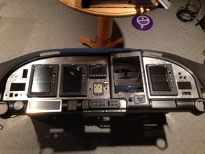
Not sure on the date of when the Aerosport panels arrived since I got rather busy with work and other things going on. My best guess is they arrived in early November.

Date Nov 7th, 2013, 16 hours

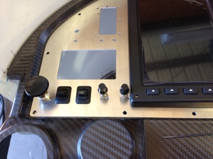
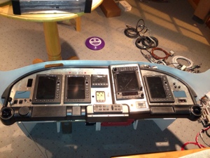
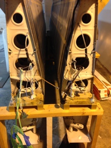
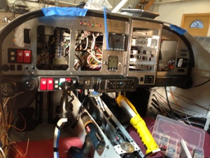
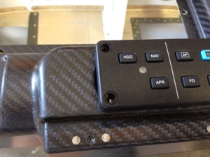
I spent much of my time beginning to understand what the task at hand was. I laid most of the components out in the panel. There were several holes and tolerances that were either wrong size (too small). Some of the holes being smaller actual was ok since I hadn’t determined the final LED signal light I wanted to use yet until I saw it on the panel. One of the dimmer control knobs is rather close to the Left PFD but this is likely a non issue.

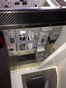
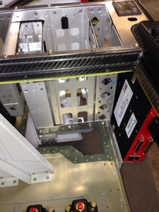
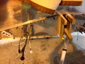
I continued with understanding how to mount the avionics trays. This took a bit of effort to get them correctly aligned where I wanted them. I used various support behind the panel to anchor the trays to each other and to the sub panels. I believe I have captured enough attach point to secure the trays and the weight they will be holding.

Date Nov 9th, 2013, 8 hours

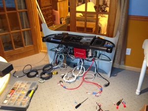
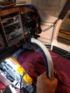
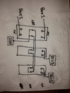
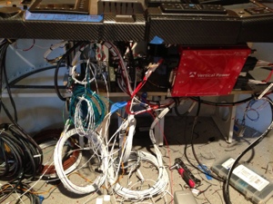
I then started on wiring. I introduced the harness to the sub panel for the first time and got a good look at the real “task at hand”. I put the VPX Pro back into place to understand how the harness routing would be effected. I did change the way I was going to originally route the harness since it quickly appeared that I could not route all the cable thru an opening I had originally thought would work. It would have worked if I had attached the harness to the back of the trays before installing them but either way the over goal was still captured. Many hours spent on basic harness routing and planning.

Date Nov 10th, 2013, 8 hours

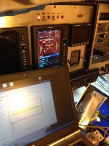
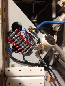
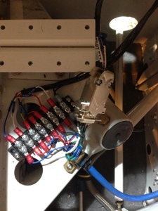
Harness termination begins. I started with connecting the VPX Pro to various connections coming from the harness. I decided to not connect the CO monitor to the GEA24 Discrete In 2 J244-42. I choose to not connect this since I have a dedicated yellow LED in the panel. I disconnected the Trim, Aileron and Flap Position sensor wiring form the GEA24 unit. The VPX Pro is sending the Trim, Aileron and Flap Position sensor status to the MFD via RS232. I removed the Main Bus Volts wiring J244-25 and Main Amps J244-36/37 to allow the VPX Pro to provide this information to the MFD.

Date Nov 16th, 2013, 8 hours

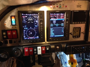
Wired the AFS AOA, CO unit and defrost fans.

20131118-172923.jpg

20131118-172943.jpg

20131118-173000.jpg

20131118-173008.jpg

20131118-173017.jpg

20131118-173026.jpg

20131118-173032.jpg

20131118-173041.jpg

Avionics G3X Components

Mounting G3X Components

Oct 27, 2013. 5 hours.

I decided I had a fairly good idea for the locations of the G3X components and so I started to lay them out on the sub panel. I tried my best to make everything fit as I thought they should be oriented for best access and routing of wires. I had to add support for the mounting of the GSU-25 to make the sub panel more rigid.

GSU 25 provides the following functions:

Avionics GNC-305 Autopilot Control Panel

Mounting GNC-305 Autopilot Control Panel

Oct 26th, 2013. 2 Hours

I mounted the GNC-305 Autopilot Control Panel this weekend. There will be an aluminum panel that will act as a face plate to help cover the hole that are used for mounting the veneer control cables since the bezel of the GNC-305 doesn’t cover them. Since i don’t have the Al plate yet I decided to cut the main mounting hole and fitted the GNC-305 in place. Simple and straight forward.

20131030-075500.jpg

20131030-075508.jpg