Category Archives: Flight Line Air Conditioning

Flight Line Air Conditioning Fuselage

Close out panels and AOA switch

April 30, 2014 3 hours

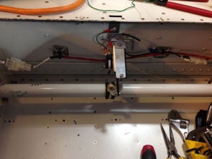
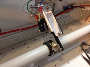
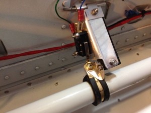
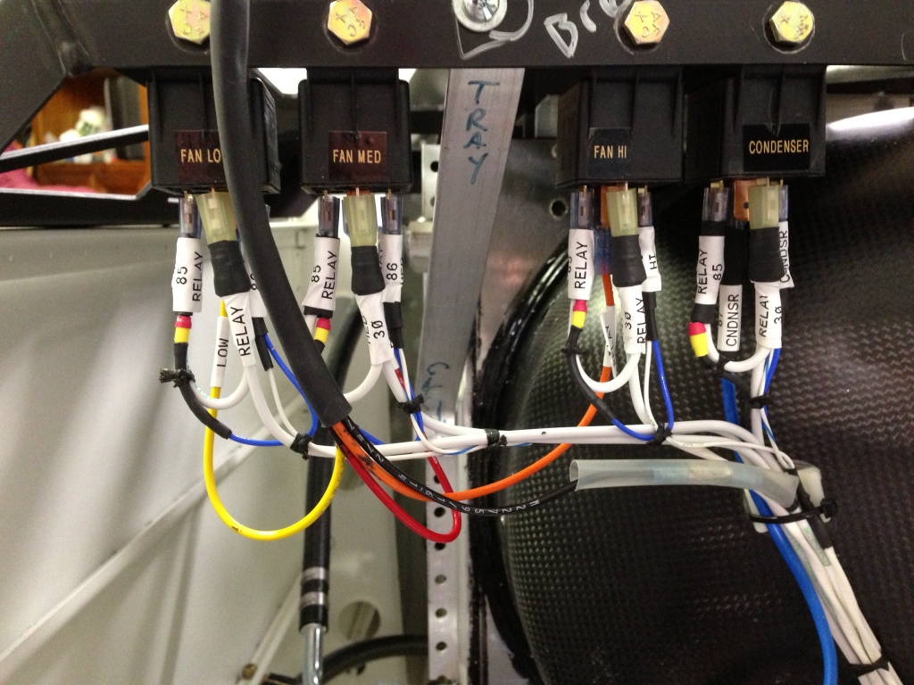
I decided it would be best to start closing up the panels in the back of the airplane along with securing the wires being routed in these areas. I also installed the AOA switch to the flap sensor so when the flaps transition out of the -3 degree setting the AOA is alerted to the configuration change.

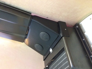
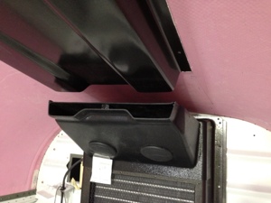
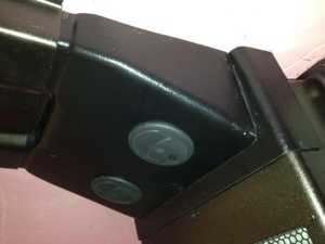
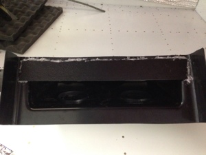
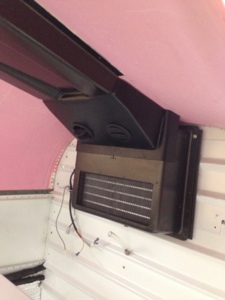
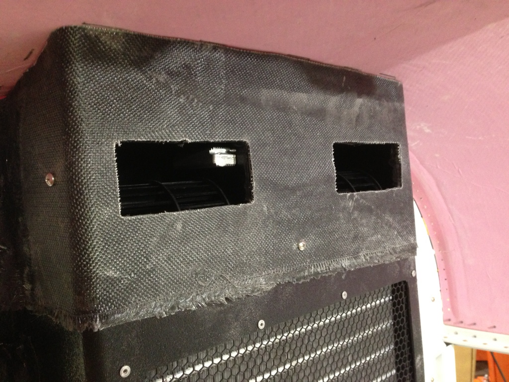
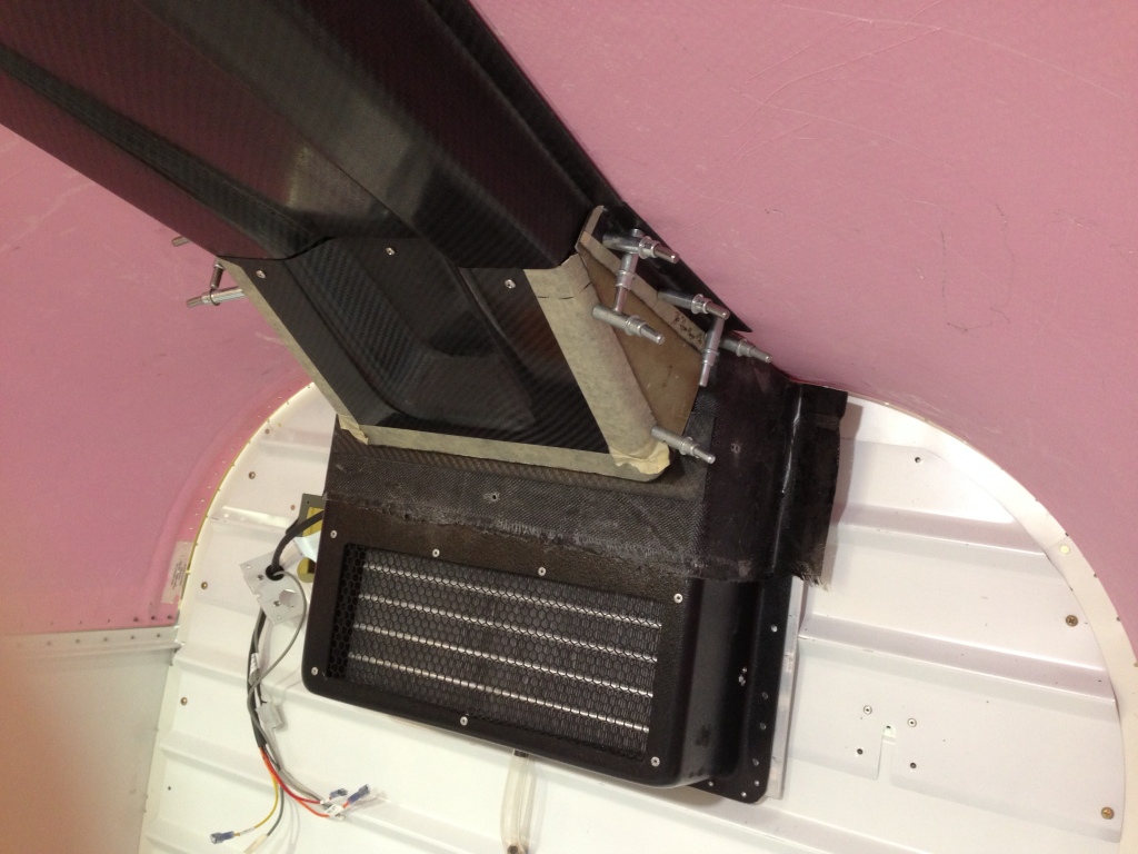
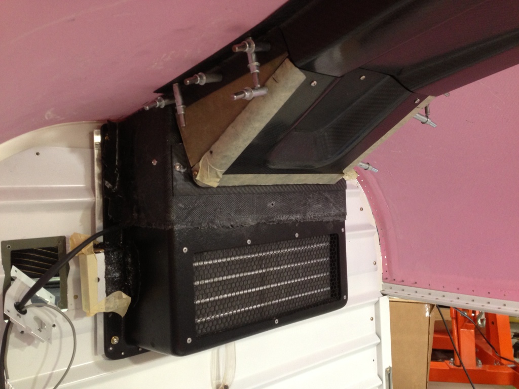
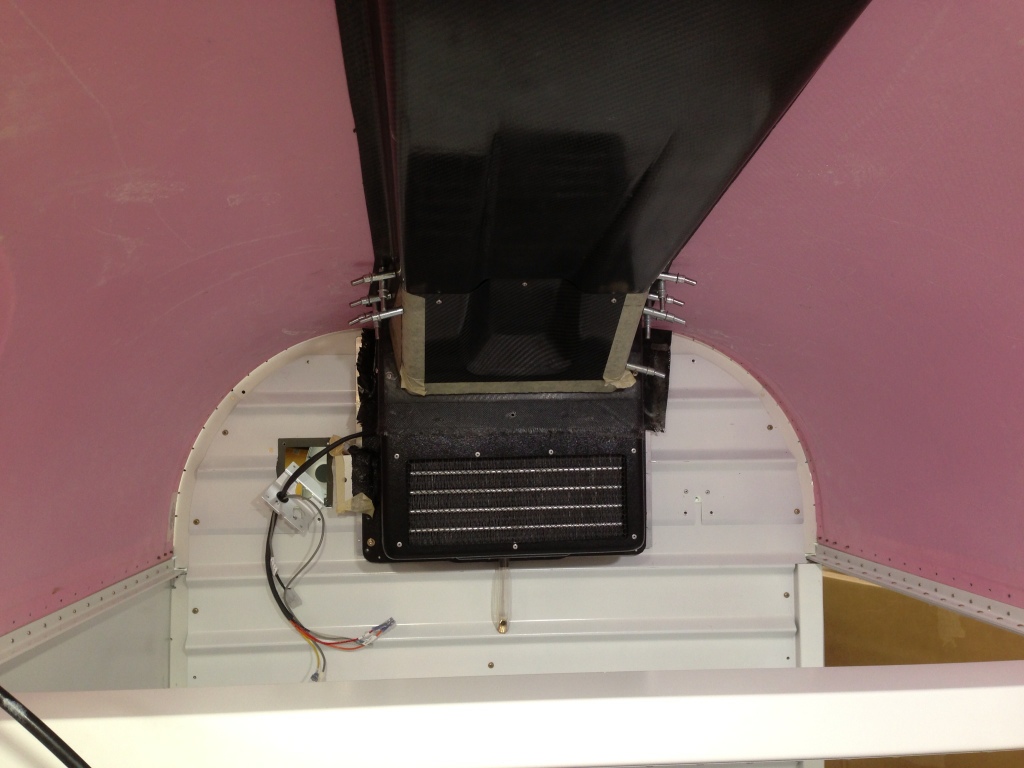
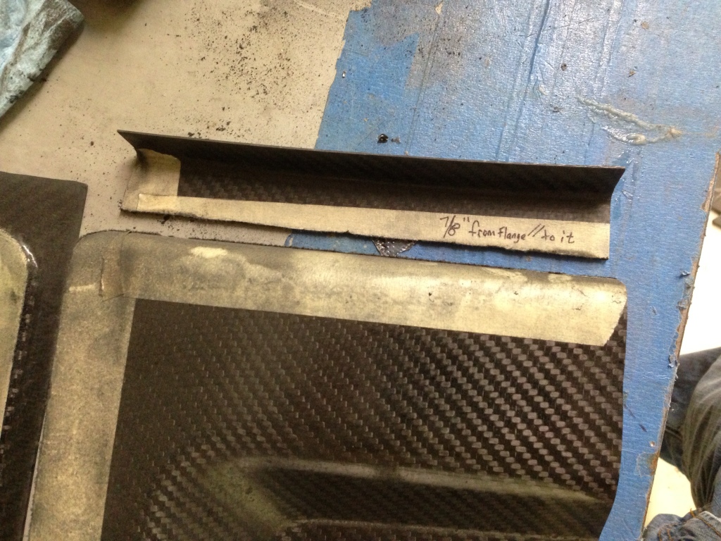
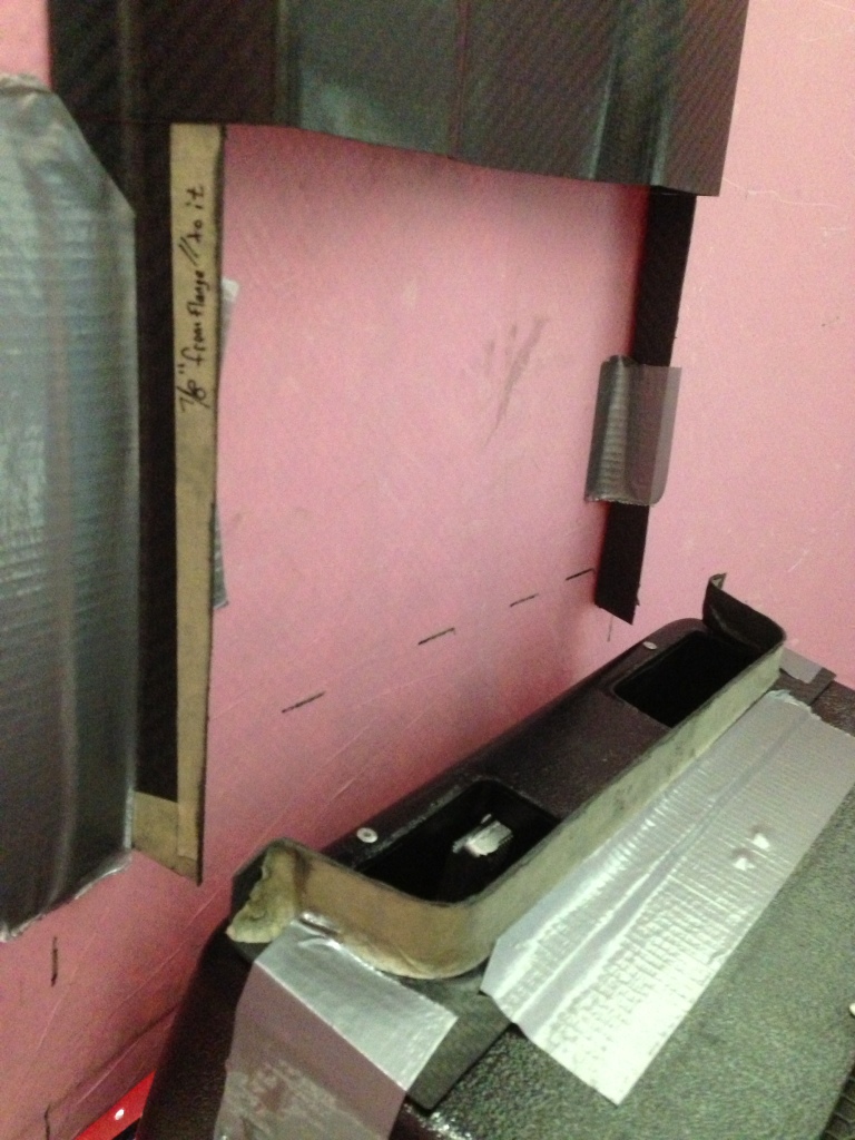
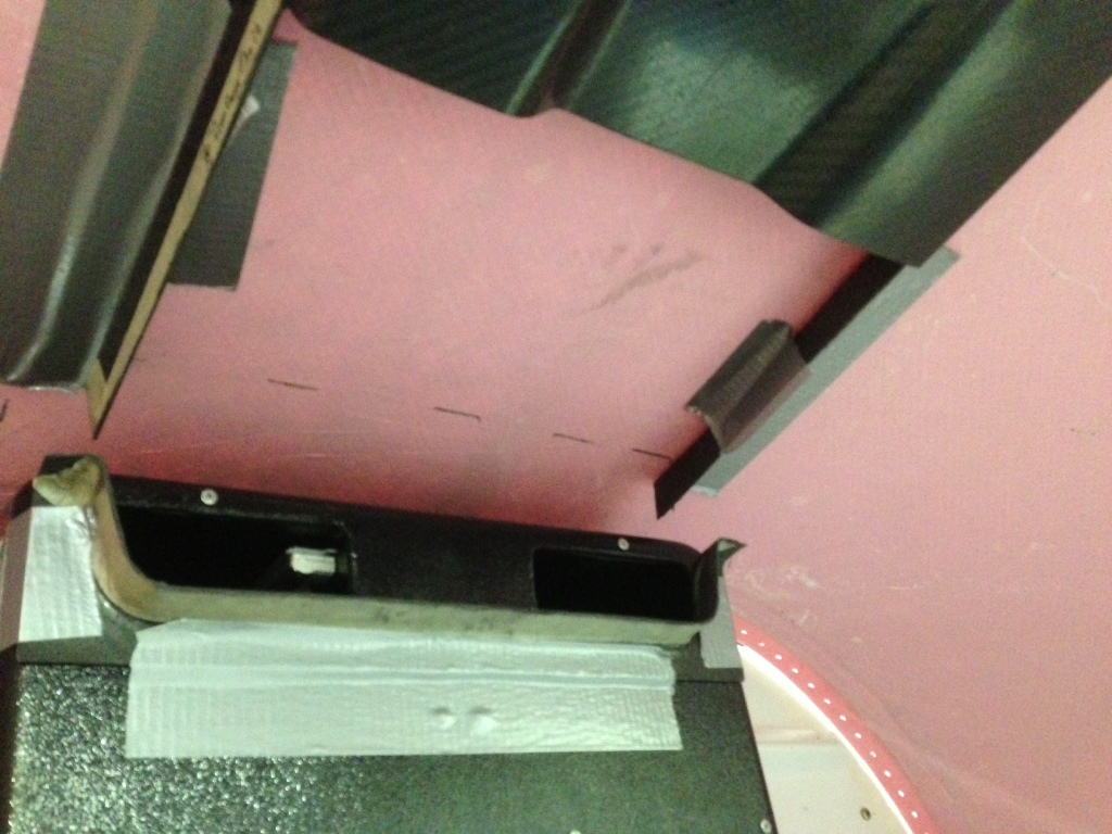
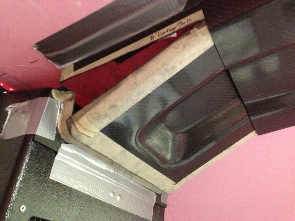
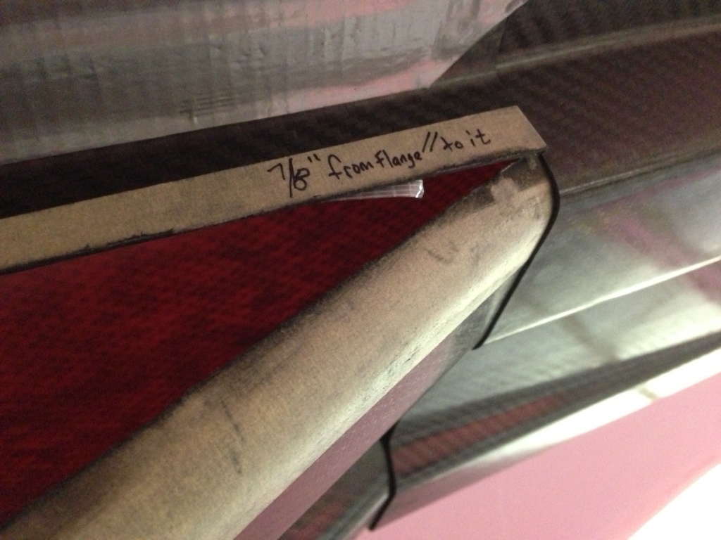
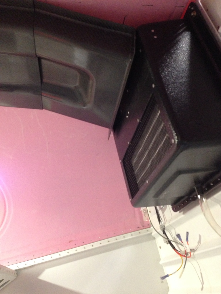
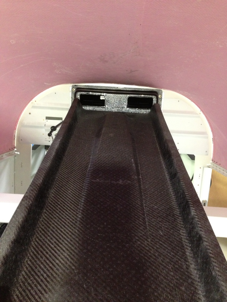
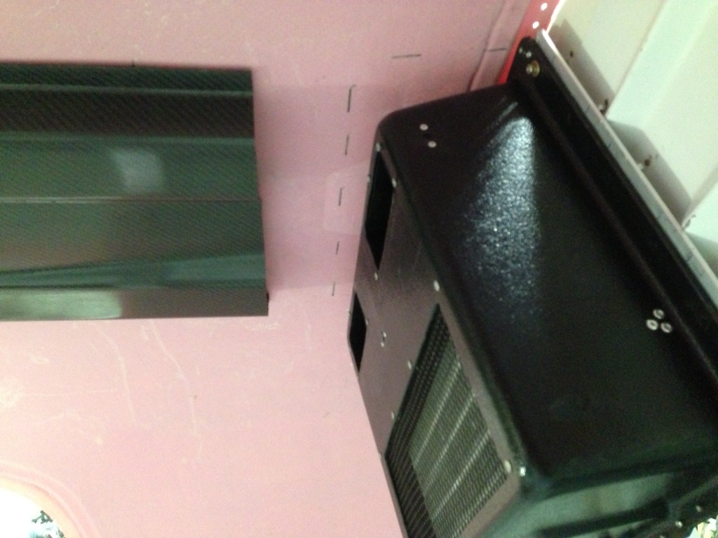
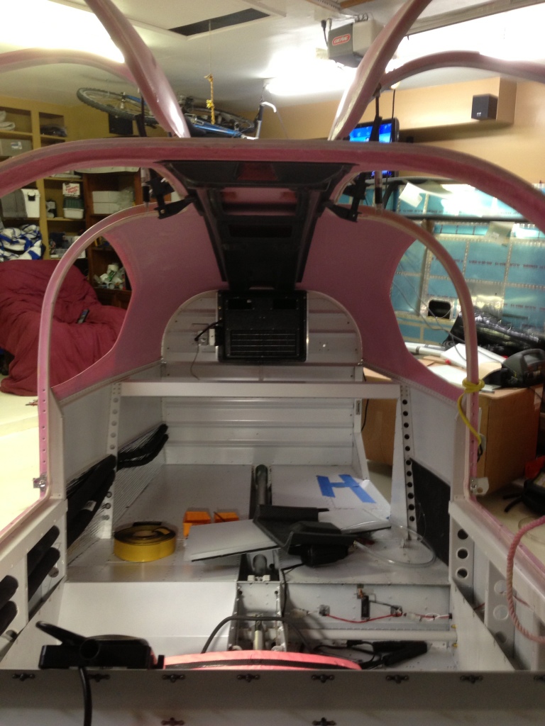
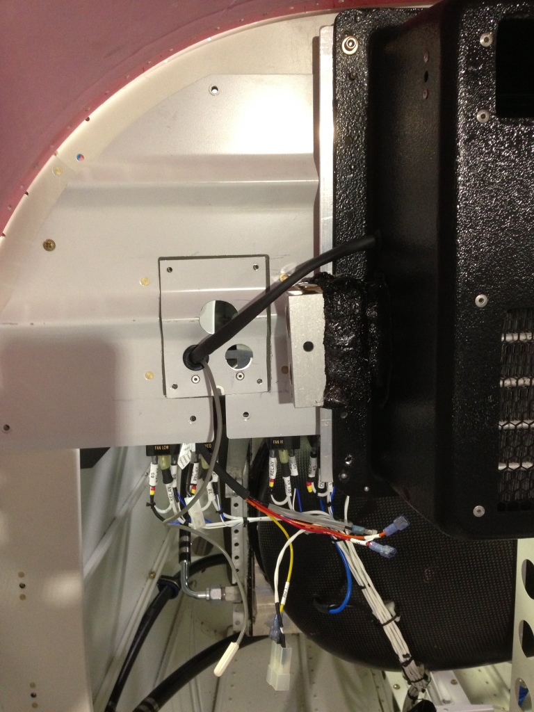
I also installed the transition from the evaporator tot he AeroSport overhead. I drilled a couple of holes and added some rubber door seals. I also installed the close out over head panels to the overhead. It looks good but sadly I scratched the overhead when I was working with the AeroSport Headliner inserts.

20140507-133429.jpg

20140507-133451.jpg

20140507-133509.jpg

20140507-133521.jpg

Flight Line Air Conditioning Systems

AC Compressor

Wednesday 26th, 2014. 2 hours

I received a replacement AC Compressor from John Strain at Flightline AC. It seems the first compressor I had received had a much larger diameter clutch pulley on it not allowing it to be mounted to the engine while using the standard “green” belt. John sent me the new compressor and I went to work fitting it to the engine. The pictures only show the ring gear as “in place” since I am working on the cowling baffling and didn’t want the prop in the way.

I had to modify the tension adjustment arm for the compressor mounting bracket since it was about 1.5 inches to long. I shortened it and re drilled the mount hole.

I had to modify the compressor mounting holes on the compressor itself. These are threaded as a standard configuration so I made the holes clearance holes so I could use through bolts.

20140402-091709.jpg

20140402-091752.jpg

20140402-091730.jpg

20140402-091720.jpg

20140402-092021.jpg

20140402-092033.jpg

Flight Line Air Conditioning Section 43, Cabin Cover Systems

Overhead cabin transitions from Evaporator

March 16th, 4 hours. I received back the molded transition piece from John at Flightline AC that was produced from the transition piece I made. Overall the piece looks fantastic but we both knew the piece would need trimming to properly fit since they made the transition piece based upon little to no extra information. In one of the pictures you can see how the original intent was to be, however based upon this installation and many other likely to follow for others the transition piece will need to be modified a bit more to be mounted much higher. I trimmed off the top portion of the piece that wraps around the evaporator. I then lowered the inside backing wall that helps seal the evaporator face to the transition since I had to raise the entire tranission up higher. The tranistion now mounts up to the overhed, evaporator and cabin top very nicely. I still need to locate a mounting plate for the front mounting hole already in the evaporator and place a rubber or foam gasket material on the surface that require to be sealed. I think John will revise his mold slightly to accomidate the angle differences but overall the tranisiton piece is very near it final shape.

John placed to vents in the transition piece to help throttle the air flow plus allow the cold air to be more quickly recirculated thru the evaporator to help cool down the cabin quicker and achive an overall lower temperature.

20130417-103744.jpg

20130417-103755.jpg

20130417-103809.jpg

20130417-103822.jpg

Flight Line Air Conditioning Systems

Flightline Evaporator to Overhead transition

Feb 23rd, 2013, 8 hours. Started the morning by using West Epoxy Systems to adhere almost all the overhead tranistions toagther. I did not adhere the ramp section to the close out panel that attaches to the evaporator yet. I still need to attach the ramp union piece to the overhead section that will remain with the overhead mounted to the cabin top. This will require everything to be in place and then some epoxy will be used to temporarily hold the angle required. Then I can final epoxy it in place to the overhead.

Flight Line Air Conditioning Systems

Flightline AC Evaporator and overhead tranistion

Friday 22nd, 2013 (2 hours.) I took the backer/closeout piece of fiberglass that connects to the face of the evaporator and cut the two air exhaust holes. Added the three holes for mounting the piece directly to the evaporator.
I then proceeded to drill and cleco all the pieces together while they were in place.

20130225-084306.jpg

20130225-084314.jpg

20130225-084322.jpg

20130225-084330.jpg

Flight Line Air Conditioning Systems

Flightline AC Evaporator to Overhead Transition work

Feb 21, 2012, worked 2 hours. Apparently the brain storming paid off at least for now. I made a couple more cuts on the largest of pieces cut off from the overhead. I trimmed the three flanges from the main overhead section that would normaly butt up to the baggage bulkhead. The side flanges are cut off to 7/8″ measured parallel to the flange. Both sides of the overhead were cut off. I then cut off the rear flange section measured 3/4″ parallel to the flange. This left three pieces that I can attach individualy to the overhead that will be used as the skeleton for the over all transition piece. Pictures are attached to help explain the process.

20130222-103533.jpg

20130222-103627.jpg

20130222-103636.jpg

20130222-103644.jpg

20130222-103658.jpg

Flight Line Air Conditioning Systems

Flightline AC overhead to Evaporator transition

Feb 20, 2012, worked 2 hours. I decided to cut back the over head another 4 inches to make the ramp angle less between the evaporator and overhead. Once the cut was made I spent the majority of the remaining time figuring out my Go Forward plan. Lots of brainstorming going on. My skill set isnt very big when it comes to this type of thing so I am limited on what experience I can pull from.

20130222-090216.jpg

20130222-090225.jpg

Flight Line Air Conditioning Systems

Flightline AC Evaporator to Overhead transition work

Monday Feb 18th, 2013 (2 hours) the overhead from Geoff Combs – Aerosport Products arrived and I quickly jumped into looking at what it was going to take for the evaporator and overhead to be joined. Not an easy project by no means since the evaporator isnt designed with this type if install in mind. The evaporator is originally designed for use in the Lancair airplanes mounted on the interior bulkhead. All other RV10’s have the evaporator installed aft of the baggage bulkhead on the AC tray. Although this does make for a very good looking package with it being mounted on the AC tray, less than good efficiency was coming from the system this way.
Now back to the task at hand, I decided the best way to approach making a transition form the evaporator to the overhead was to trim out the differnce from the overhead the amount that the evaporator sticks out from the baulkhead. This came to about 6 inches and I decided to add three more inches thinking this might be far enough in front of the evaoprtor to make the inlet air ramps fit. I will need to trim out more as it turns out. I then fitted the overhead to the cabin top and lets just say that Geoff did a fantastic job on the overhead, fits very well. I am in the process of making a shroud that can act as a back plate that will wrap around the evaporator front face and sides. I will then match the shroud to the cabin top and cut out the two air exhaust holes that match to the evaporator. I am hoping this will act as the “back wall” to the tranisiton.

20130219-071607.jpg

20130219-071615.jpg

20130219-071621.jpg

20130219-071628.jpg

20130219-071636.jpg

Electrical Flight Line Air Conditioning Systems

Flightline AC system tray, flap sensor, and flap motor wiring

Feb 16th, 2013 (8 hours). Started the day with wiring all the electrical components on the Flightline AC system tray located behind the aft baggage bulkhead. I had already wired the condenser relay so I was only concentrating on the evaporator fan 3 relays and the switch located on the dryer. I needed to pull new wire from the front of the fuselage to the system tray and this took longer than expected since my little helper (Casey) had tugged on one of the “fish tape” lines I had previously ran thru the conduit under the aft baggage area. Once I got back on track with the wire pulls I was able to pull 4- 2 conductor cables as needed for the AC controls.
I wired the three relays, low, med, and high fan connections to the control lines from the CB-1 controller that will be mounted in the panel up front. I then ran the power wires from the aft circuit breaker board located just below the AC tray up to the relays. I wired in diodes across all the relays since the relays only have an internal resistance and not a diode. The wiring diagram shows they have internal diodes but looking at the data sheet for the specific relays I was shipped shows otherwise.
The dryer located on the aft section of the AC tray has a “sensor switch” that helps keep the system safe in operational parameters by sensing the low and high pressure of the system. I don’t know the technical term for it so I will just call it a switch for now. This sensor switch is connected to the circuit breaker board below the tray and fused at 5 amps, it then passes thru the sensor and makes its way back to the front of the AC to be connected to the relay that will control the compressor. Relay Pin 85 will have the sensor connected to to it, Pin 86 will be connected to CB-1 Pin 2.
A sensor (thermister) is placed just in front of the evaporator for sensing the return air, this sensor allows the CB-1 to try and maintain a set temperature. It will control the compressor as needed off/on to allow for the system to become more efficient.
I finished the AC wiring and moved to the flap motor and flap position sensor wiring. I ran 1- 2 conductor and 1- 3 conductor cables from the flap sensor and flap motor locations up to where the Vertical Power (VPX-Pro) future location. Simple process but time consuming.

20130218-080334.jpg

Flight Line Air Conditioning Systems

Flightline AC, Access panel pass thru for hose and wire evaporator connections.

Friday 15th, 2013 (4 hours), I worked on cutting the pass thru holes for the high and low pressure evaporator lines plus the fan electrical wires and thermister sensor. I initial made the two holes for the pressure lines and then added the pass thru for the wires once I figured out where the pressure lines needed to be. Simple process and was done rather quickly. I then concentrated on the hose routing in the tray area. I cut and crimped all the connection points required aft of the baggage bulkhead wall and finalized the routing of the hoses. I will add more pictures to this posting later, not all taken at this point.

20130218-071922.jpg

20130218-071930.jpg

20130218-071944.jpg

20130219-065645.jpg