Category Archives: Mounting Avionics

Avionics Mounting Avionics

Panel Work continued

Nov 20-25. Hours 48

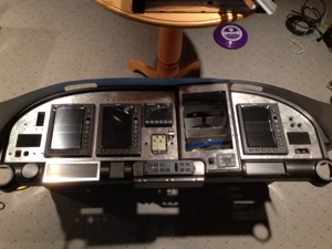
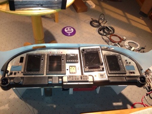
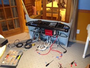
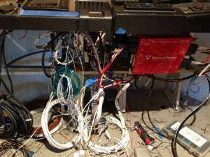
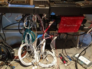
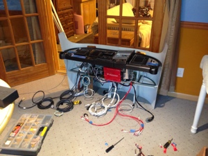
I continued working the panel with routing of wires and termination of various system wire to various system parts. I was able to connect many of the VPX-Pro connections but will still have mare to terminate once the panel fuselage piece is riveted in place. I terminated as many wires as I could for the O2 system and CO system while I had the panel laying in the apartment hangar.

I had to correct a couple of pins that connect to the Garmin GMU22. A ground wire and RS232 wire was in the wrong locations from Stein. I added the O2 and CO2 audio wires to the PMA8000BT audio panel. I wired the passenger audio mute function on J2-13,14 together. AUX enable goes low when AUX button is on. May be used for passenger mute inhibit by connection to pin 13.

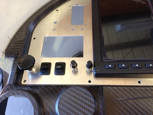
I wired in the Cabin 2-way light switch and the Tie Down light switch plus a switch to control the AC Compressor independent of the AC Control module. This switch will light up (internal led) when the AC Control module is commanding the AC Compressor on, but the AC Compressor will not turn on until the switch is filled up to the ON position. This is so I can control the AC Compressor and know when the AC Control module is commanding it to be on.

I removed several of the voltage and amperage measuring wires from the GAD29 since the VP-X will handle the processing of the information and then hand off this to the G3X.
20131203-070822.jpg

20131203-072324.jpg

Avionics Mounting Avionics

Aerosport Panels Arrive

Not sure on the date of when the Aerosport panels arrived since I got rather busy with work and other things going on. My best guess is they arrived in early November.

Date Nov 7th, 2013, 16 hours

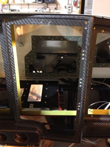
I spent much of my time beginning to understand what the task at hand was. I laid most of the components out in the panel. There were several holes and tolerances that were either wrong size (too small). Some of the holes being smaller actual was ok since I hadn’t determined the final LED signal light I wanted to use yet until I saw it on the panel. One of the dimmer control knobs is rather close to the Left PFD but this is likely a non issue.

I continued with understanding how to mount the avionics trays. This took a bit of effort to get them correctly aligned where I wanted them. I used various support behind the panel to anchor the trays to each other and to the sub panels. I believe I have captured enough attach point to secure the trays and the weight they will be holding.

Date Nov 9th, 2013, 8 hours

I then started on wiring. I introduced the harness to the sub panel for the first time and got a good look at the real “task at hand”. I put the VPX Pro back into place to understand how the harness routing would be effected. I did change the way I was going to originally route the harness since it quickly appeared that I could not route all the cable thru an opening I had originally thought would work. It would have worked if I had attached the harness to the back of the trays before installing them but either way the over goal was still captured. Many hours spent on basic harness routing and planning.

Date Nov 10th, 2013, 8 hours

Harness termination begins. I started with connecting the VPX Pro to various connections coming from the harness. I decided to not connect the CO monitor to the GEA24 Discrete In 2 J244-42. I choose to not connect this since I have a dedicated yellow LED in the panel. I disconnected the Trim, Aileron and Flap Position sensor wiring form the GEA24 unit. The VPX Pro is sending the Trim, Aileron and Flap Position sensor status to the MFD via RS232. I removed the Main Bus Volts wiring J244-25 and Main Amps J244-36/37 to allow the VPX Pro to provide this information to the MFD.

Date Nov 16th, 2013, 8 hours

Wired the AFS AOA, CO unit and defrost fans.

20131118-172923.jpg

20131118-172943.jpg

20131118-173000.jpg

20131118-173008.jpg

20131118-173017.jpg

20131118-173026.jpg

20131118-173032.jpg

20131118-173041.jpg

Avionics Interior - Aerosport Mounting Avionics

The Start of Mounting the Avionics

8 hours, Oct 19, 2013
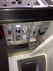
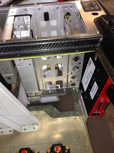
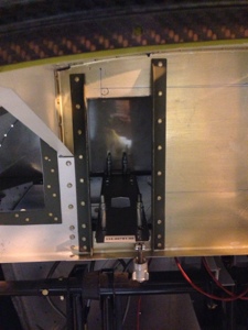
While I was letting epoxy dry on the cabin top I decided to start working on installing some of the basic avionic units in the sub panel area of the front panel. The GTS-800 weighs about 9 lbs and I was very concerned with the weight and balance issue and where I could mount the “brick” with good structural integrity. The GTS-800 comes with a tray mount to make the unit as a Line Replaceable Unit -LRU. I decided to used the bottom tray since it would hold the unit nicely and allow for a somewhat easy way for me to mount everything. Although the tray added more weight this was the best option since I had to span a distance from one of the cross members in the panel to the firewall. The picture explains what occurred to get tit mounted. I had thought about mounting it back on the empty spot on the air conditioner tray but the weight and balance numbers weren’t very favorable for this.

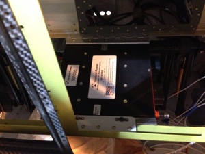
I moved on to mounting the VPX Pro. I thought I could mount the box near the right side of the sub panel but I quickly realized this wouldn’t work because of the wires coming off the unit plus there was minimal room with push pull cables in that area also for controlling heat vents. I decided to locate it very near the center of the sub panel just behind where the veneer controls would go and this is also the location where I am placing the GMA-305 autopilot control panel. I hinged the VPX box to the middle support structure and hard mounted a tab that the VPX will attach to near the front panel. This should allow for access to the avionics equipment mounted higher in the panel.

20131022-075036.jpg

20131022-075043.jpg

20131022-075051.jpg

20131022-075058.jpg