Category Archives: Avionics

Avionics Interior - Aerosport Mounting Avionics

The Start of Mounting the Avionics

8 hours, Oct 19, 2013
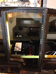
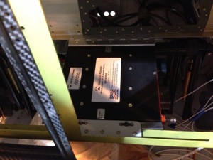
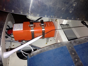
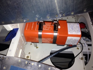
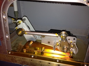
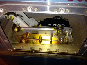
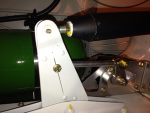
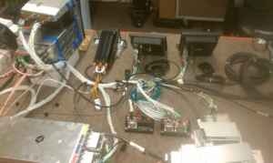
While I was letting epoxy dry on the cabin top I decided to start working on installing some of the basic avionic units in the sub panel area of the front panel. The GTS-800 weighs about 9 lbs and I was very concerned with the weight and balance issue and where I could mount the “brick” with good structural integrity. The GTS-800 comes with a tray mount to make the unit as a Line Replaceable Unit -LRU. I decided to used the bottom tray since it would hold the unit nicely and allow for a somewhat easy way for me to mount everything. Although the tray added more weight this was the best option since I had to span a distance from one of the cross members in the panel to the firewall. The picture explains what occurred to get tit mounted. I had thought about mounting it back on the empty spot on the air conditioner tray but the weight and balance numbers weren’t very favorable for this.

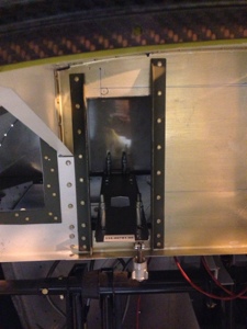
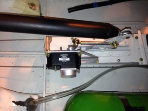
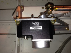
I moved on to mounting the VPX Pro. I thought I could mount the box near the right side of the sub panel but I quickly realized this wouldn’t work because of the wires coming off the unit plus there was minimal room with push pull cables in that area also for controlling heat vents. I decided to locate it very near the center of the sub panel just behind where the veneer controls would go and this is also the location where I am placing the GMA-305 autopilot control panel. I hinged the VPX box to the middle support structure and hard mounted a tab that the VPX will attach to near the front panel. This should allow for access to the avionics equipment mounted higher in the panel.

20131022-075036.jpg

20131022-075043.jpg

20131022-075051.jpg

20131022-075058.jpg

Avionics GTS-800 TAS

Mounting GTS-800 TAS Antenna

7 Hours, Oct 5th. Diving into the Garmin GTS-800 Traffic Alert System. This is an active interrogation traffic system that will reach out to other transponder equipped systems to locate and gather telemetry data from them for display on the GTN-750 screen. Unlike many of the other traffic systems (Mode S) the GTS-800 will work in an environment where Mode S is not available. For instance on the ground and other remote locations not covered by Mode S. I feel that although this system is costly and heavy it is worth the safety investment when flying Class B and other heavy traffic situations.

I started to mount the GTS-800 TAS top antenna and quickly referred myself to the many install manuals that Garmin uses for the GTS-800 system. I also referred to Sean Strasbourg (SP) GTS-800 install for guidance on the top antenna ground plane that is required. Sean gave a great write up on his top antenna install and I did my best to copy it word for word. I basically attached a sheet of aluminum to the top of the cabin with rivets and epoxy. I then glassed over the aluminum and am in the process of blending it into the cabin top.

On the underside of the cabin I had to cut out an area so that I could attach the VERY expensive 90 degree coax connectors to the antenna. There are four cables running up to the antenna. Sadly I will need to cut the connectors off the end of the coax since I cannot properly route the coax as planned with the 90 degree connectors. I am a little upset that this is required but Stein wanted to test the system prior to sending it to me. Fair enough I guess. I purchased 4 new 90 degree connectors. This area is also getting epoxy add back to seal up the cabin and add back strength.

I moved on to mounting the bottom antenna. The Garmin manual states no more than a maximum of 8 feet horizontal distance is allow between the top antenna and the bottom. I am just at 7 feet difference because we will have the MotoPod belly pod going on and off the aircraft. I had to place the bottom antenna far enough back to be clear of the pod movements. The Garmin manual also states the vertical alignment should be centered for both antennas but the bottom is off by about 2 inches. This was because of the structural support near the where the autopilot is mounted too and the fact this is where the elevator push rod is connecting to the rear most elevator push tube connects. I still need someone to help pound the rivets for the doubler plate for the bottom antenna. And I need to keep working on blending in the top cabin epoxy.

20131022-073238.jpg

20131022-073251.jpg

20131022-073259.jpg

20131022-073308.jpg

20131022-073320.jpg

20131022-073327.jpg

Avionics ELT- ACK Technologies

Installed the ELT – ACK Technologies

Sept 29th, 2013. 8 hours

Installed the ACK Technologies ELT under the vertical stabilizer where many other RV10 builders have placed it. Created 4 stand offs so the ELT could be raised to fit into the given spot. I routed the 4 pin telephone cable to the front panel and mounted the ELT antenna. I have yet to route the GPS signal wire to the ELT since that is part of the Avionics harness that is not installed yet.

20130930-143739.jpg

20130930-143745.jpg

Avionics Wire Routing

Various Cable Routing throughout Fuselage

Sept 28th, 2013, 8 Hours

I received from Stein various wire I had previously order with the avionics that was mistakenly left out of the initial shipment so i went about running it throughout the fuselage. I routed a 5 conductor shield wire from the MH Oxygen bottle to the controller that will be mounted on the panel. I then ran the four separate cables required for the 4 individual controllers to the main control head in the panel.

I routed the rudder trim, 5 conductor no shield wire. I routed the pitch trim servo, 5 conductor no shield wire. The pitch servos wire runs near the pitch servo (GSA-28) and has a 9 pin connector inline near the the pitch servo. The reason for the 9 pin connector is for an entry point for the GSA-28 servo “trim” white wires to be connected to the elevator trim. Essentially the GSA-28 servo wire already has the four control wires (2 wires to the trim switch in this case VPX-Pro and 2 wires to the trim servo itself). Since the GSA-28 has an auto trim feature it needs to be connected between the switch and trim servo so it can auto trim and allow the user to trim the elevator also.

Avionics Pitch Servo - GSA 28 Roll Servo - GSA 28

Install of Roll and Pitch Servo – Garmin GSA 28

Sept 26-27, 2013. 2 Hours

I installed the Garmin GSA 28 Roll and Pitch servos. Printed out the RV10 install instructions and sat down by the wing and installed the GSA-28 Roll Servo with minimal issues in the wing. The GSA-28 install in the tail cone area of the RV10 was a little more of an issue since I have the Airflow Performance AC installed that sort of interferes with gaining access to that area. All nuts/bolts torqued to manufactures specs and marked with torque seal.

I did go back on Sept 28th and install the proper washer and nut, torqued and torque sealed the horizontal pushrod connector bolt seen in the photos.

20130930-095202.jpg

20130930-095207.jpg

20130930-095215.jpg

20130930-095221.jpg

20130930-095227.jpg

Avionics Panel Design

Defrost Vents

Sept 25th, 2013. 2 hours

Added the defrost vent holes to the glare shield. Easy process to measure then cut. Not much more to say than that.

20130927-131512.jpg

Avionics

Stein sent me some “stuff”

Sept 23rd, 2013. Received the shipment of Avionics we ordered from Stein. 4 boxes that contained a bunch more boxes. Somewhere in all the boxes and stuffing was the actual shipment. Garmin loves to use a 1’x6″x10″ box for a 2″x2″x2″ part.

Unpacking all that stuff was Christmas/Birthday in September. The entire family was involved as we sifted through the boxes. Very exciting.

20130927-112107.jpg

20130927-112117.jpg

20130927-112136.jpg

Avionics EDS-4ip Mountain High Aviation Oxygen System

Mountain High Refill Station

Sept 14th, 2013. 1 hour
I finally ordered the replacement 1/8″ compression Ferrule so i could finish installing the 1/8″ refill line from the refill station to the tank. All lines flushed and torqued per manufactures guidance – Swage Lock. (3/4 turn after finger tight and tubing not moving)

00HDW-02120BB – 1/8″ Comp Ferrule Back Brass
00HDW-02120FB – 1/8″ Comp Ferrule Front Brass

20130924-094930.jpg

20130924-094940.jpg

Avionics

Avionics at Steins Facility

September 5, 2013
I was sent a brief update by Danny Jones who is providing the wiring harness as dangling wires for our avionics configuration. It is exciting to see this coming together and am even more excited to start installing it. Danny has a couple more items to work but will be ready to ship sometime in September.

20130910-141140.jpg

20130910-141150.jpg

Avionics EDS-4ip Mountain High Aviation Oxygen System

Center Console Mountain High Oxygen System air connections

Aug 31, 2013. 6 hours
The 4 oxygen control pulse units from Mountain High Oxygen will be mounted in the center console since this provided the most logical location for the units versus work required for other locations. The hose routing went from behind the rear baggage bulkhead to the flap control tube then over to the center tunnel. I temporarily placed the tubing and several cable tie mounting brackets since I will later come back and run the communication wire for the units. I also ran black tubing inside the tunnel to accommodate the wire run up to the dash where the control head will be mounted. This tube will also house all the headset jacks along with music audio input jack for the rear seats.

20130910-135322.jpg

20130910-135335.jpg