Engine Details -none at this time, no engine purchased yet!
Category Archives: Engine
Engine Section 46, Engine Mount and Landing Gear
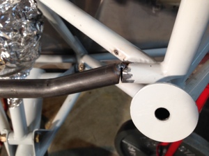
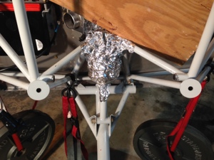
Engine Cold Air Sump Modification to Engine Frame Mount
March 10, 2014 – 11:07
Feb 8th 2014. 3 hours
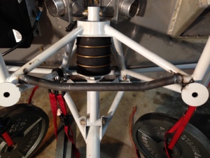
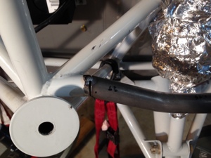
Wally Wostal (my mothers cousin) came over to weld in the modified lower cross member for the engine mount. He mad a quick job of it and was done in about 1 hour just for the welding portion. It turned out great and I later painted it with epoxy primer.
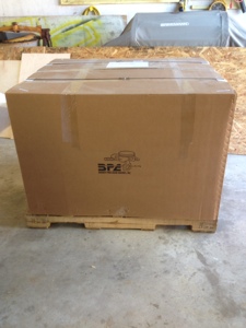
BPA Engine Arrives !!!!
January 20, 2014 – 10:28
Jan 17th, 2014. 1 hour.
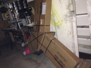
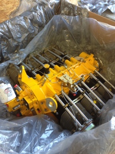
The engine arrived nicely packaged in a large box surrounded by foam. It took a while to get it out of the box since my engine hoist would not fit around the base of the box and crate. I had to cut the foam out from around the bottom of the engine to get the hoist under it all.
After working with Robert at EFII and Allen/Rhonda at Barrett Precision Engine we decided to send the engine down to me since running the engine with the EFII system and the Dyno setup would have not proven anything different from when Barrett first ran the engine with the EFII system. The engine was ready from Barrett on Nov 27th. After many communications between all parties involved the conclusion to why there where some difficulties with the first engine run was because of how the engine is operated on the dyno versus what the EFII ignition system was expecting during normal operations.
My understanding to the situation was the engine run in on the dyno locks the engine in under a high load so the engine can reach temperature quickly for proper ring break in. During this operation the MP is somewhere below 24″ most of this time causing the timing curve to not be retarded by 4 degrees to more of the normal mag timing. The engine was run at 30 degrees timing and at under a high load it caused the engine to have a pre ignition event on the number 1 cylinder likely because this cylinder might have been slightly leaner than the others. Normal operation would have kept the engine at a “squared” operation and would load the engine differently. The solution to running the EFII system on the dyno is to either disconnect the MP sensor to the ECUs causing the ECUs to run at standard mag timing to to load a “dyno map software” load.
The engine was painted yellow by Barrett and we let them pick the actaul shade, we just asked for “yellow”. What color we got we really liked.
Medium Chrome Yellow
Omni MAE (Acrylic Enamel) (PPG)
Brand code: 80502
It is originally a Chrysler color and the OEM code is DT2279
I recievd in the box,
EFII complete system
Ring Gear
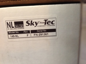
Starter (SkyTec 149-NL, Ser No FN-291361)
Cold Air Induction and FM300

EFII ECU mounting
January 20, 2014 – 09:47
Jan 19th, 2013. 8 hours.
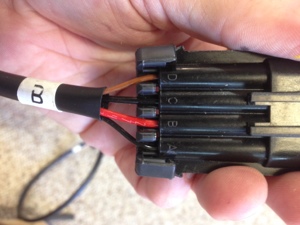
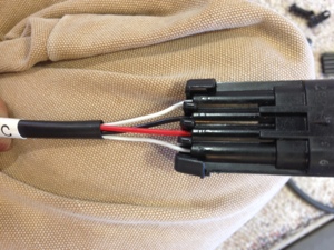
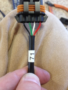
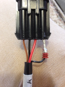
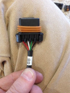
I punched two holes through the firewall and installed the pass through connections for a tight seal around the wires. I punched one hole for the routing of the GPS/XM antennas that will be mounted on a shelf. The other hole was for the EFII wiring harness. I didn’t like the large outer shielding for the EFII harness nor did I like the mounting pass through to be used in the firewall. I trimmed off those pieces and routed the wires through the sealable firewall pass through I mounted on the far top copilot side.
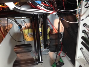
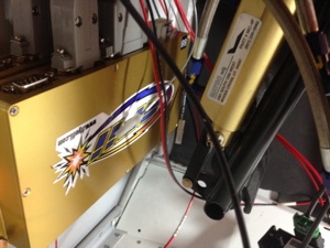
I mounted the both ECU boxes under the copilot side of the dash. They are on the firewall just forward of the brake pedals. The brake pedals in all of their possibly movement are 1.5 inches away from the boxes. I had heavy aluminum angle down there for backing the forward firewall mounted battery so I used this as the attachment point. Although not as easy as I would have hope to have access too the location still works well so far. By the way those ECU boxes could survive a bomb blast I think. They likely could have the bottom portion of the box machined a little more to take off some of the weight of the boxes.
Engine and EFII Ign
December 31, 2013 – 09:29
Dec 31, 2013. (1 month delayed)
Engine and EFII update. The engine was ready for delivery just prior to Thanksgiving but I decided to have the EFII Dual Ignition system installed at Barrett so they could run it on the dyno. With a couple of wiring issues on the dyno the EFII system did not operate at full throttle. It is believed the power source for the IGN coils (three of them) was not adequate enough to supply ample power to the coils at the higher RPM ranges. Thus causing the engine to run perfect at idle and lower RPMs but at higher RPMs it failed to operate correctly.
All the EFII parts including the ring gear were sent back back to Robert where he bench tested the units once again. He originally did this prior to shipping them out to Barrett. Nothing was found to be an issue and so the parts are en-route to Barrett. I am not sure if Barrett will have the time to dyno the engine with the EFII systems but it would be a great comparison to the mag dyno run.
Time will tell if the issue was related to smaller than recommended gauge wiring for the EFII setup on the dyno, but I am behind now on the project because of this set back. I was originally going to use the time my dad spent with us for the holidays to mount the engine while I worked the avionics. Over 1 month set back.
Robert at EFII and Rhonda and Allen at Barrett have all been great to work with throughout this and have been very responsive.
Our Barrett Precision Engine (BPA) comes to life !!!!
December 4, 2013 – 14:13
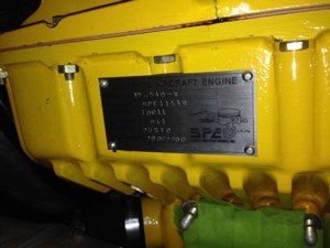
Today I received a call from Allen, owner of Barrett Precision Engine, to let me know that our Lycoming IO-540-X engine, S/N BPE-11358 came alive today (Dec 3rd, 2013) on the dyno stand at Barrett. I don’t have the official paper work but he advised me the engine produced 301.93 HP @ 2701 RPM. Allen mentioned this is one of the best 9:1 compression Lyc IO-540 engines he has built. Regardless of the comment I am extremely happy with the results.
I originally had the EFII dual ignition system installed by Barrett so he could run the engine with the system. I believe this would be the first time Barrett has run the EFII system. Everything went fine until 2400 RPM. So the system was removed, mags put on and then run for initial break in. The EFII system is being sent back to Robert and they will give it a once over and verify if anything is amiss. Either it is a system issue or install issue but regardless I look forward to seeing the resolution to the problem soon. I was hoping Barrett would put the engine back on the stand with the EFII system installed so we can confirm proper operation and get a comparison against the mag run. I have confidence it’s not a system or install issue but likely a wire labeling issue or something that simple that caused possible crank sensors to be connected wrong. This is an assumption on my part…. We shall see…
-
Engine Data from build:
Built Factory New Limits
New Cylinders
All mandatory parts replaced plus any additional parts not meeting new parts limits
New Airflow Performance fuel injection system, FM-300
BP’s patented Cold Air Induction
9.1 compression cylinders
Sky Tec 149 NL starter
Dynamic balanced rotating assembly
Bonaco Fuel Lines – Tunnel
September 24, 2013 – 09:42
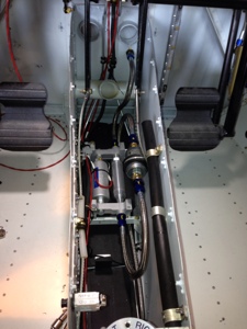
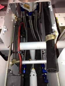
Sept 14th, 2013, 3 hours.
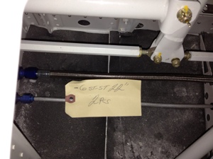
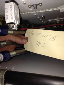
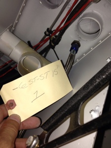
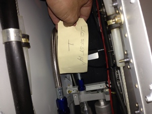
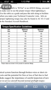
I received custom fuel lines from Bonaco that I specifically order to match the fuel system layout in the tunnel and under the seats. The fuel lines are made with PTFE inner hose, outer stainless shielding with a plastic outer shielding and -6 connections. All measurements where spot on for the layout of the system. All connections torqued and marked with yellow torque seal.
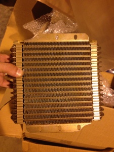
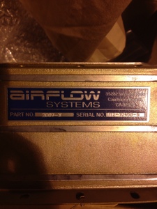
Engine oil cooler mod
August 26, 2013 – 14:51
8/25/2013, 1 hour.
I started looking at mounting the engine oil cooler. It is the Airflow Systems 2007-x model. It is slightly larger than stock model and the mounting tabs need to be trimmed for it to fit onto the oil cooler box. The oil cooler box needs to be trimmer as well and have the upper attach tabs removed and placed higher up onto an angle bracket to capture the top mounting holes of the oil cooler. I started working on modifying the oil cooler.
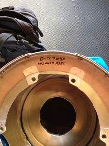
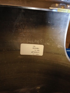
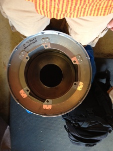
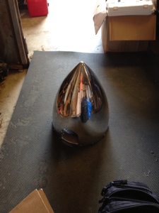
Spinner (D-7709P) and prop gov arm (C-4582-P)
August 22, 2013 – 20:26
Today I received the prop spinner (D-7709P) and prop governor arm (C-4582-P) from our local prop shop, R&D propeller located in Pearland, TX The spinner is special order since it is for the Show Planes cowling and it requires a ~15″ diameter spinner. While it wasn’t cheap it sure looks very nice in its polished state and in its 15″ size. I almost was set back when I noticed how large the spinner actual was. I hope it doesn’t look to big in front of the RV10.
Prop Arrived
August 9, 2013 – 00:42
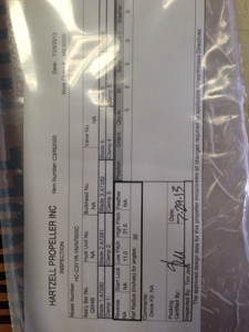
On August 5, 2013, the propeller arrived from Hartzell. This is the HC-C3Y1R-1N//N7605C a composite prop with a stainless core three bladed prop. I ordered it through Vans and it shipped directly from Hartzell.
The 15″ spinner will be coming from a local shop in Pearland, TX at Pearland Regional Airport. This is a polished spinner. The reason it is 15″, actually something more like 14.7/8″, is because of the Show Planes RV10 cowl that I will be using. I also order a control arm from Hartzell that will be sourced from the Pearland shop. The control arm is P/N: C-4582-P and the spinner part number is D-7709P.