Engine Details -none at this time, no engine purchased yet!
Category Archives: Engine
Engine
AC Compressor Hose, Engine wire Adel Clamps
April 21, 2014 – 07:06
April 18th, 2014. 16 Hours
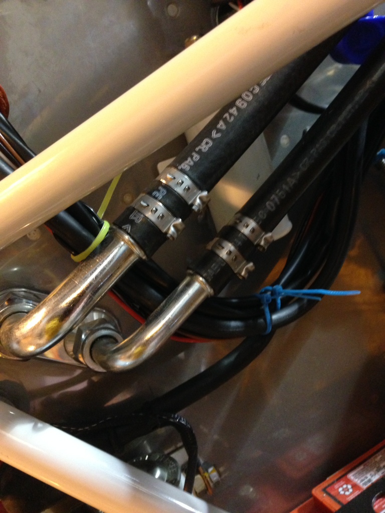
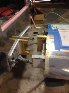
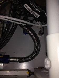
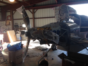
My parents came in for the Easter weekend so my dad and I started cleaning up some of the wire routing around the engine. Various Adel clamps were placed to hold the spark plug wires and various other sensor wires around. I continued to work on the engine air intake tubes by adding three nut plates to the pilot side intake to snorkel tube. I decided since we had just changed the AC system in my truck and had all the vacuum equipment that we should draw a vacuum on the AC system in the plane. SO I crawled into the tail section of the airplane and finalized all the wire by zip tying them into place along with adding the transponder cable and antenna. Used my dads help to fasten the antenna since I needed two people to tighten it. Attached the inlet and outlet hose for the condensor and we filled the dryer up with about 2 oz of oil since we could not get all the oil into the compressor that we wanted in the AC system. I then attached the inlet and outlet hose to the dryer. I cromped the two hoses to the compressor. My dad then drew a vacuum on the system. Last we checked the system was still holding good vacuum after we disconnected the vacuum pump.
Routing of engine sensors, spark plug wires, AC hose
April 16, 2014 – 10:51
April 13th, 2014, 18 hours
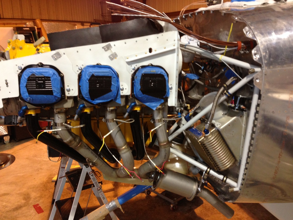
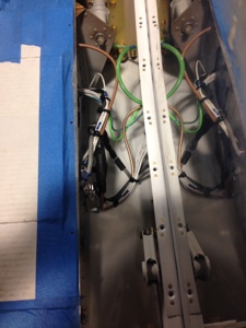
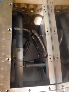
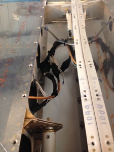
Started routing the thermocouple wires for EGT and CHT wires along wi the fuel flow sensor. Routed the spark plug wires and added tie wraps to the locations where I want to use ADEL clamps.
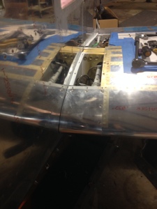
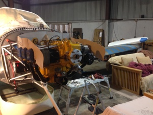
I worked on various engine baffles in the front of the engine. Added the rubber baffle material to the two side front baffles and the two baffles over the front of the engine.
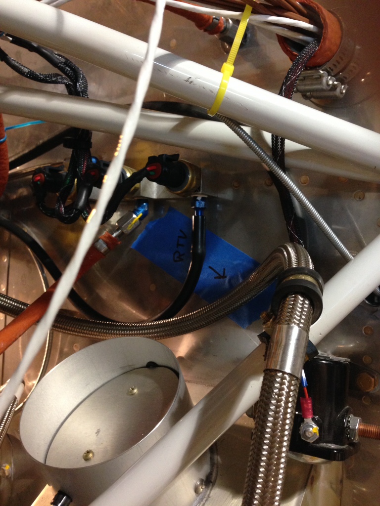
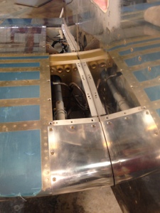
Routed the air conditioner large and small hose from the firewall to the compressor. I had to punch holes in the copilot side rear engine baffle to allow the hoses to pass thru. I also punched a hole for the EFII crank timing sensors to pass thru. Ultimately these holes will be sealed with red RTV once all the hoses and wires are ADEL clamped in place.
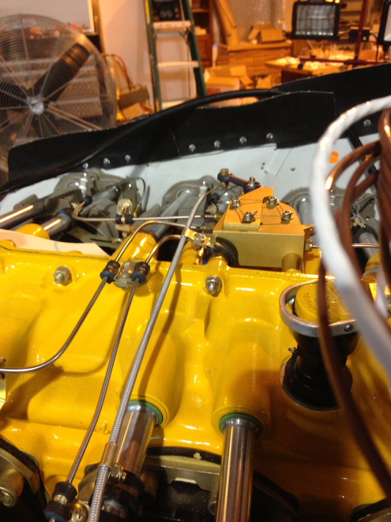
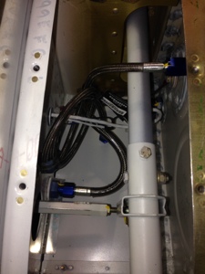
Routed the manifold pressure hose from number 5 cylinder to the EFII dual MP gauges and add a “T” and routed the off shoot to the G3X MP sensor mounted on the firewall.
I ordered engine fuel hoses from TS Flightline all fire sleeved.
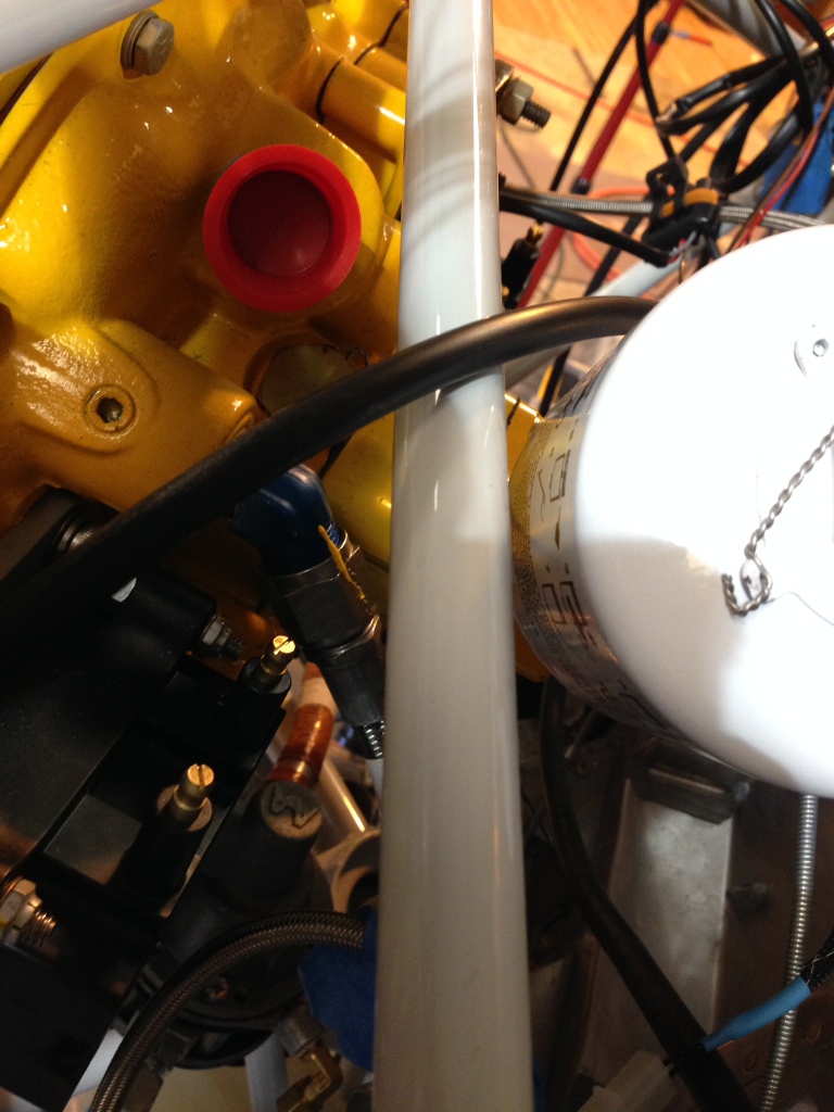
1) Mechanical fuel pump to fuel servo
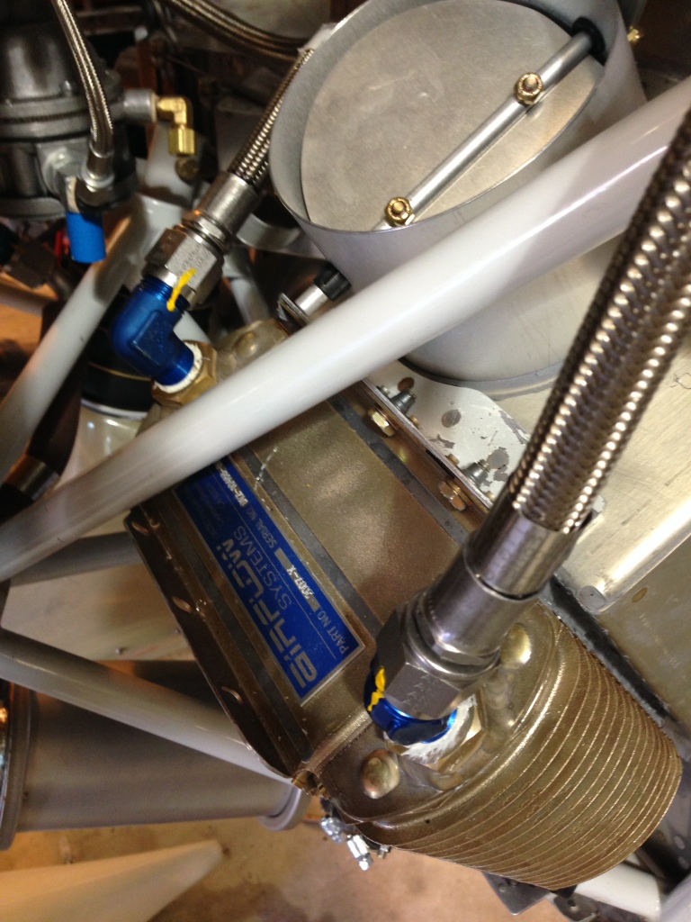
2) fuel servo output to the red cube, R12204C5.5, -4 str/90′ f/s
3) red cube to purge valve input, R12204C16F, -4 str/90′ f/s
4) red cube output to firewall, R12204A46F, str/str f/s
5) firewall to left side fuel tank “t”, R12204A50, -6 str/str
6) mechanical fuel pump to fuel pressure gauge, R12204A12F, str/str
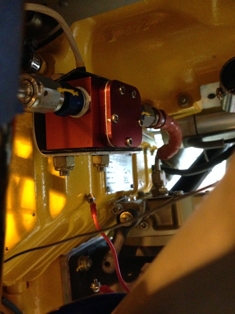
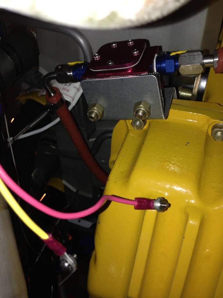
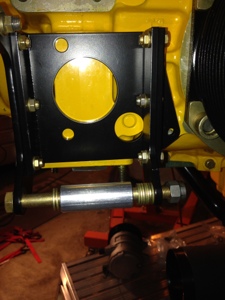
Fabricated a red cube mount bracket. I wanted to let the red cube be supported by the hose but it seemed to floppy to me so I made a bracket. I mounted the red cube to the bracket using rubber so that it might be cushioned more so than if it was directly mounted to the bracket. I used aluminum and am sure it will crack advetualy but I will be watching for it.
Misc Engine items completed
April 16, 2014 – 10:27
April 9th, 2014. 3 hours
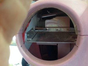
Worked a couple of misc items on the engine. Final fitted the oil cooler lines just after I filled the oil cooler with oil. Sadly did not capture the amount of oil the oil cooler contained… Maybe 3/4 a quart. Fastened and torqued the oil line on e cooler and back on the engine.
Drilled two screw holes into the oil cooler air flow valve and inserted two screw to hold it in place.
I am getting ever so close to finalizing the inlet air scoop for the engine. Cut then Fiberglas and repeat.
Exhaust muffler install and Purge Valve Control Cable Install
April 8, 2014 – 12:47
April 5th, 2014, 6 hours
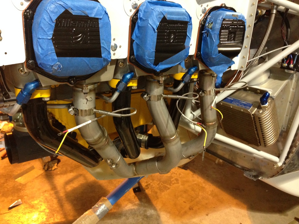
I had to fabricate up two supports for the two mufflers. I used a 3/4″x3/4″ angle aluminum to be the support the each muffler. The install went failure well but included lots of piecing it together then taking back apart to fit it as I went. I hate dealing with those darn rubber clamps!!
I had already routed the Purge Valve cable though the firewall and so decided to push forward and run it through the baffling as well. I then used several ADEL clamps to secure it to the push rod tubes and up to the Purge Valve. With a little tweaking I was able to get a very smooth cable pull and positive closure and open adjustment.
EGT and CHT sensor install
April 8, 2014 – 12:40
April 3rd, 2014, 2 hours
After torquing down the exhaust pipes I installed the EGT and CHT sensors in the cylinders and exhaust pipes.
Induction Cowl Work conti, exhaust installed
April 8, 2014 – 12:36
April 1, 2014, 2 hours
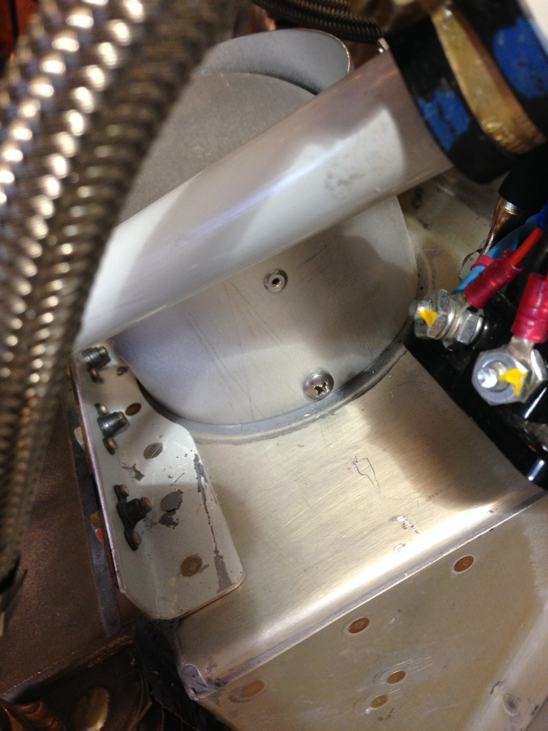
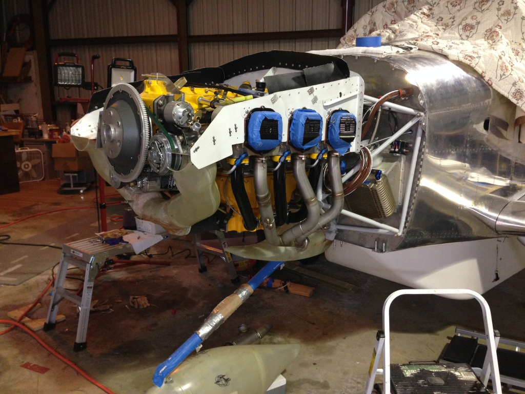
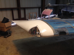
More inlet cowl work to be had…. Rough fit the pilot side induction cowl after trimming it for the AC Compressor.
I installed the new Vetterrman Exhaust that Client built up for me in an amazing short time. 1 week! Install went great.
ShowPlanes Cowling Work Oil Door
March 25, 2014 – 14:44
March 24, 2014, 1 hour
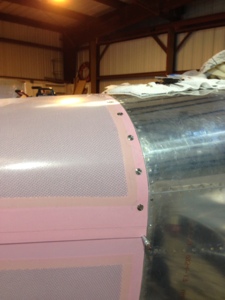
I worked on fiberglass for the right side cowl induction of the ShowPlanes cowling. I then moved to the oil door and started to trim it down to size.
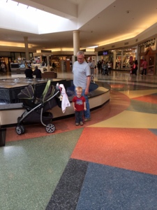
I did have a little help 🙂
ShowPlanes Cowling Work
March 25, 2014 – 14:41
March 17th to 23rd, 120 hours
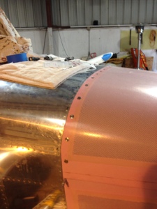
My dad and I mostly worked on the baffles and cowling top and lower halves. What a surprise this was to me since I had thought this was going to be much easier than it is.
My dad started working on the MotoPod, exchanging two plates that were incorrectly supplied to us. He placed the cable covers on and lubed the cables just prior to closing it all up. He then moved on to pulling off all the blue protective tape on the wings that had been there since we received the parts.
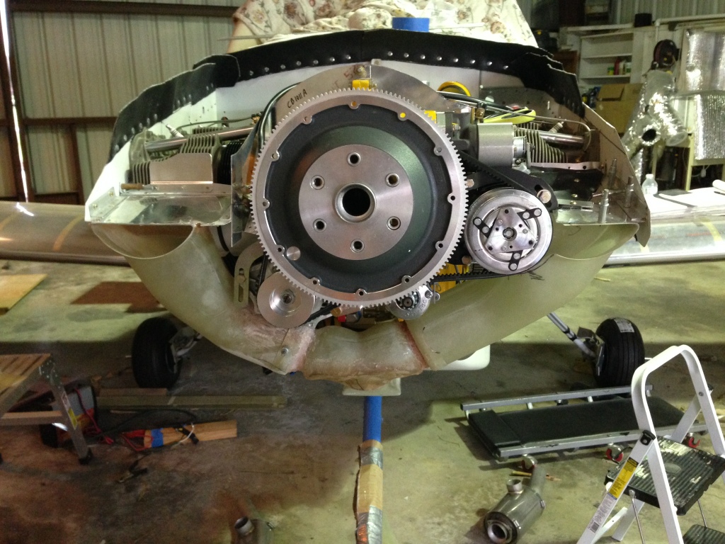
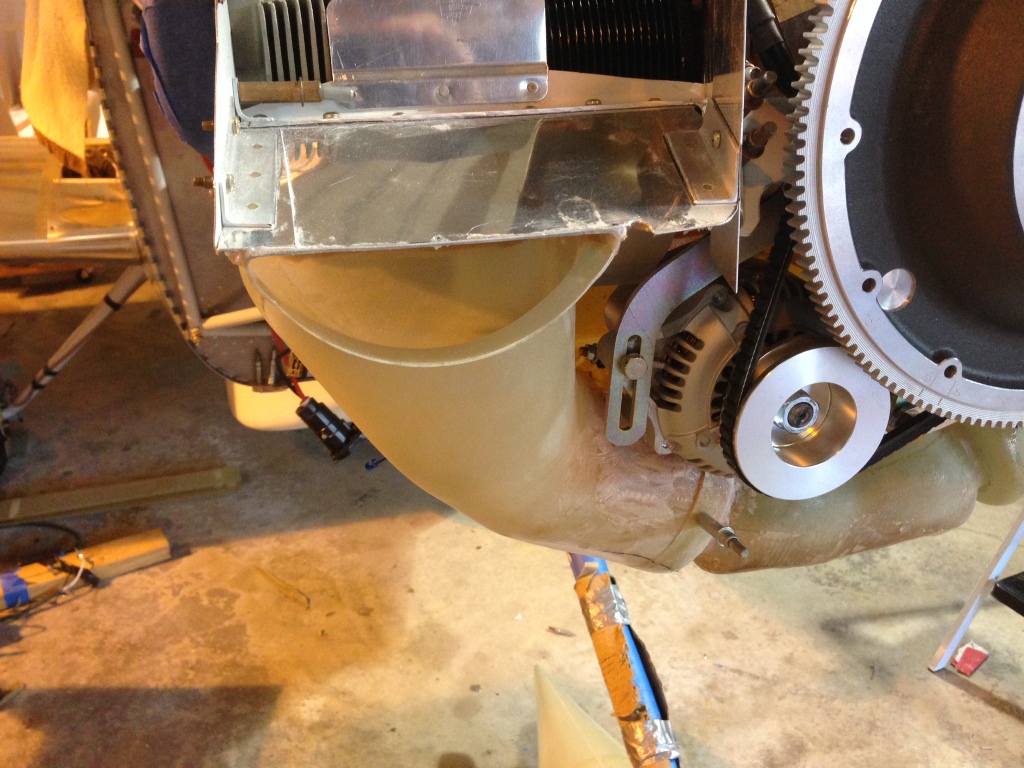
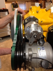
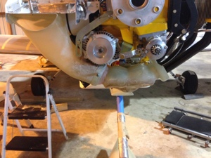
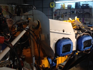
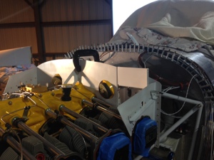
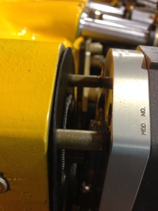
We then both started working on the top and bottom cowl halves since it was easer to work using two people. I had purchased SkyBolts for the top firewall half and drilled the final mounting holes in the cowling. Sadly I realized after it was to late that I had not properly positioned the cowling so I had to fiberglass the holes back full and start over again. The Show Planes cowl is a great product and easy to work with and is easy customizable. It was required that I grind off several places where the Skybolts back plates mount so they would set properly. While I was working on cutting the cowling my dad started installing the Plane Power Alternator, 70 AMP. He then moved over to installing the AC Compressor. He looped the drive belts around the ring gear and alternator but could not get them around the AC Compressor. It was later realized the AC Compressor that we had (Alpha I believe) had a larger pulley on it than what is currently shipping from FlightLine AC. Flightline promptly shipped a new compressor out to me. Sadly we could not mount the compressor so we could further work on the left side of the cowling air inlet ramps.
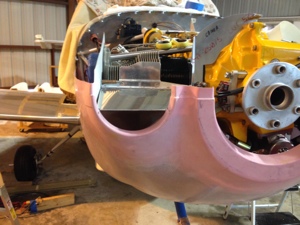
I started concentrating on the right side air inlet ramps. With the ShowPlanes cowl there is a special inlet scoop that comes from the left and right side down to the engine fuel servo. I though the right side would be easy….. well not really… but I am figuring out how it should have been thus making it much easier than how I was going about fitting it all. I figured it out how I wanted to make the inlet ramp for cooling air and engine induction air should be the only issue was how to hold all the movable parts together long enough to get an idea how it wants to be all attached. With everything in place and the bottom cowl on it makes for a rather tight fit. The instructions call for about 1/8″ clearance for engine movement. This seemed a little small so I increased the space and thus am having to rework fiberglass.
Meanwhile my dad was attaching the baffle rubber material as we had a good lower and upper cowl fitment and repeatability for mounting it all. The bottom cowl was attached using the hinge method on the side with one screw fastener on each bottom firewall point. The tope cowl got the Skybolts as mentioned above. And the lower inner portion that wraps around the landing gear had the pressure recovery mold attached to the airplane bottom with clecos and screw fasteners. This all created a good secure cowl for finishing the air inlet ramps.
Overall we had a good work week but we certainly have much more to get done before we are finished with the cowl and baffles.
Father and Son building time togather
March 10, 2014 – 13:20
Feb 28th – March 7, 150 hours.
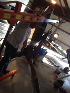
This is the week my folks came up to welcome home Brooklyn. My dad understood what needed to be accomplished and went straight to work. He didn’t need much direction so I was able to spend time with my wife, son and new daughter before pressing on with the build. My wife REALLY wants her husband back and my parents completely understand that getting this RV10 finished will help my family.
My dad worked on baffling over the engine, I painted parts of it as he completed the first steps of the assembly process. We soon found at that we needed the cowling installed before we could cut the baffling down to size. We also started to realize how much modification and change from the plans the air conditioning system was going to drive for the baffling and cowling.
I worked on the preparing the wings for the final bolts to be installed. I messaged the wing to fuselage fairings for several hours getting them to fit properly. We then pulled the drift pins and installed the final bolts to hold on the wings. I had place a call into Vans because the bolts were bottoming out on the thread and the nut was being torqued against the shaft of the bolt. Vans advised use to add washers as needed. We did this to the NAS1309-58 bolts and still had many threads left on the bolt after nut was torqued. The NAS1306-58 bolts added also but only a single thread was left after properly torqued. I did order in “L” washers in case these needed to be changed. Flaps were final fitted and installed and rigged. Ailerons were removed to allow the removal of the blue protective covering and then reinstalled and torqued. I spent some time on balancing the control sticks and push rods for the ailerons. After some time i was able to get the ailerons and flaps aligned.
I attached the right wing tip to the wing and as I had hoped the wing tip aligned very nicely with the aileron.
My dad worked on the motoPod when he came upon questions for me when I wasn’t around, so he was very busy most all the time. He was able to rig the motoPod with all the cables and pulleys. The only thing still remaining is some cover plates need to be fastened to the pod. He even was able to attach it to the aircraft and operate it up an down.
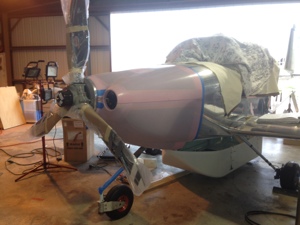
Prior to the cowl work, I un boxed the prop for this first time. I attached the back plate of the spinner to the prop per the Hartzell instructions. I decided to place only one washer aft of the spinner plate and two washer forward. This way if I have and issue with clearance after the cowl is attached I can always move washers for and aft to make the spinner clearance work better. We hund the prop and only snug fit the bolts for inital cowl work.
One of the last things my dad and I did before my folks left for South Texas to return home was to attempt attaching the cowling. I am using the new Show Planes cowling and we are supposed to use the standard vans instructions to install it. Some of those instructions are applicable so I applied the ones I thought were needed and then used pictures of other peoples Show Planes cowling being installed. We were able to get the cowl on and trimmed to a rough fit. The rough fit is nearly perfect. I am now dealing with figuring out how I want to attach it to the aircraft. The cowling has a pressure relief cowling around the landing gear and so this still needs to be fitted since the cowling will be fastened to this inner cowling as well. We still have th induction intake and filters to install. The AC Compressor is throwing a HUGE wrench into how this part is installed since the compressor is in the same space the induction air inlet left side ramp is.
Various Work Accomplished
March 10, 2014 – 12:32
Feb 15th, 2013. 8 Hours
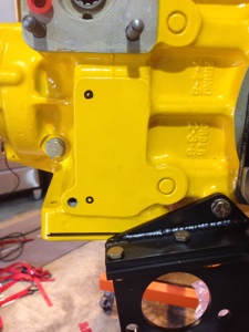
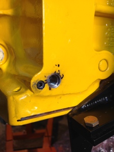
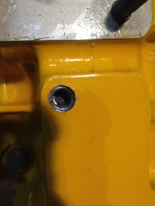
Drilled holes in the engine accessory pad for AC Compressor mounting. Barrett was to have drilled the holes but it slipped past them so I drilled them (2). Top hole had 1/8″ diamter drill bit penetrate all the into the crankcase. Barrett said to lock tight the threads and it will be ok.
Mounted the Prop Servo after I received longer standoffs from Barrett.
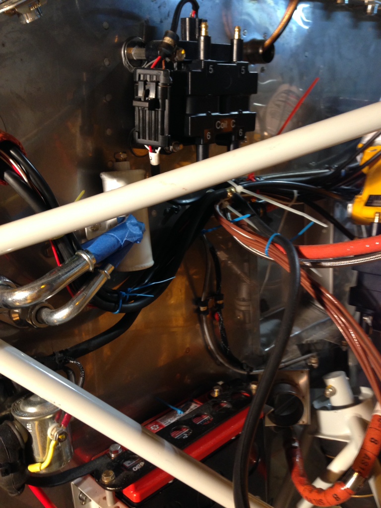
Mounted the EFII ignition coils. Mounted two of the onto the existing mag holes. Mounted the third onto the firewall.