Engine Details -none at this time, no engine purchased yet!
Category Archives: Engine
EFII Uncategorized
Engine
Engine Baffling Work Requird
July 8, 2014 – 08:19
10 hours, July 5-6, 2014
I started working on the engine baffling by removing the pilot side inlet ramp and associated rubber ramp that goes over the AC compressor. I threw it all in the trash to force myself to come up with a new design. I spoke with Nick and Dave about what needed to be corrected and dove into making the changes. Once I had the pilot side inlet ramp off, I trimmed the vertical angle piece covering some of the cylinder face and then went about threading the lower baffling rod that keeps the baffling wrapped tightly around the cylinders. There were large gaps in the baffling since the inlet ramps were pulled back away form the front cylinders causing the cylinder to not be wrapped properly.
I readjusted the lower portion of the cylinder baffles on both sides and now have the very well conformed and fitted to the cylinders 1,2 and 5,6. I then started working the pilot side inlet ramp redesign. ONce that was completed I then moved over to the copilot side and moved the inlet ramp inward and filled the gaps there. I used red RTV to sealed all the extra holes that could be letting out extra air where t wasn’t being used properly to cool anything. Two tubes used and I think I have most all the holes sealed.
The top cowling needed to have the inlet ramp cross sealed so air wouldn’t be dumped out the other sides without even hitting the engine. I correct this by putting a wall in the upper inlet ramps. I then added rubber baffling seal material to the pilot side upper ramp to help cover and make the air flow less turbulent over the AC compressor.
I believe I have almost all of the work completed that will make a huge difference in the cooling of the cylinders. I still have a couple of very small tweaks I want to make to the cowling but will see how the current changes effect the cooling first.
I also tightened the AC compressor belt and routed the low pressure line under the engine to allow the pilot side inlet ramp less obstruction. I had to order more hose and will charge the AC system once I have the new hose installed.
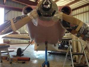
Engine hung on airframe
June 20, 2014 – 08:19
2 hours, 14 Feb 2014
Hung engine on airframe. Minimal issues to hang engine. Torqued and cotter pinned the nuts according to Vans instructions.
Engine run
June 9, 2014 – 11:33
2 hours, 6 June 2014
First engine start while on the airframe. With a watchful eye and help from my dad we prepped the airplane for first engine start. Dave Forster, my neighbor and local EAA Tech Counselor was on hand as another watchful eye.
Had I used a checklist for first engine start I would have remembered to Turn on the ignition and ECU switches. Otherwise the start was quick and uneventful.
First engine run we didn’t want to run the engine above idle until oil temp was over 100. It NEVER got there before the cylinder temps got to 300 where the engine builder told me the ground run limit should be.
Second engine run was later in the day and we started with 94 degree oil temp and ambient cylinder temps. Oil only rose to 98 and I went ahead and went up to 1700 RPM to cycle the prop. After about 8 cycles of the prop lever the prop never cycled. Wee dedicated that another engine run was required because we needed the prior working correctly and needed to verify max rpm.
We ran the engine on the June 7 with good luck as I had read on he VAF chat group about the Hartzell wanting a higher RPM to move the oil into the hub. I ran the engine to 1800 and on the third cycle of the prop lever the prop started to cycle. All this was done prior to the CHT reaching 300F.
We ran the engine once ore to set the max rpm. It is now reading 2690 RPM on the ground with full power. Again we kept the CHT below 300.
Engine run completed until first flight.
No issues at all other than prop pitch adjustment.
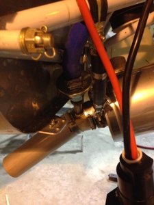
Anti-Splat Air/Oil Seperator
June 2, 2014 – 13:37
4 hours, 24 May 2014
I installed the Anti-Splat Air/Oil Separator and exhaust valve. I changed the mounting structure that held the right side exhaust muffler and pipe to accommodate the Oil Separator drain tube and valve. I also changed the routing of the oil and air drain tube routing and added a section of the aluminum pipe to the blue hose as to route the house out away from the firewall and then back again to the valve that connects to the exhaust pipe.
Wrapped the Red Cube
May 7, 2014 – 13:39
May 2, 2014. 4 hours
Performed misc work this day. Wrapped the red cube with fire sleeve. I used stainless steel clamps to hold the black fire sleeve. Secured several more hoses in the engine compartment since I had received in another shipment of Adel clamps.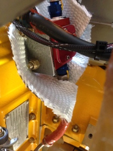
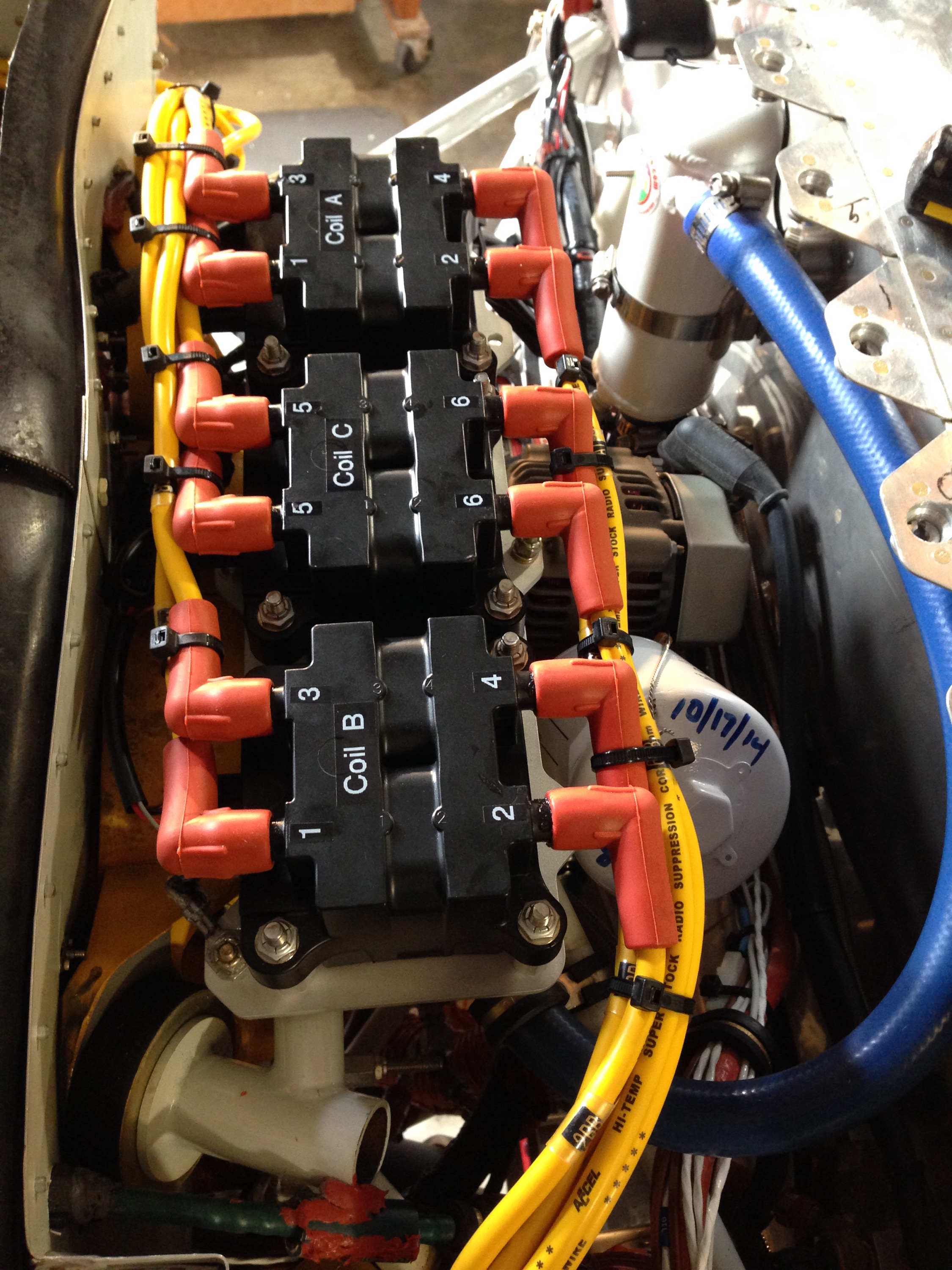
Air Inlet Engine Intake, RPM sensors, Alternator Field Wire
April 29, 2014 – 09:30
April 28th, 2014. 3 hours
I started the evening by putting in place the inlet air intake for the engine. This was the first time I installed the air inlet since the AC compressor and Alternator belts had been tightened. Sadly I had to modify the pilot side air inlet since the back side contacted the ac compressor. More epoxy and fiber. On the copilot side air inlet I added a reflective two ply aluminum foil to protect it from the close proximity of the #2 exhaust pipe. I am not sure how the foil will work but I am hoping the “Sticky Stuff” and epoxy around the outer edges will hold the foil in place. Time will tell. I plan to use this same stuff on the engine cowling near the exhaust pipe and mufflers. This is left ver radiant barrier used in our roof. I did a flame test and it passed.
I moved to connecting the Alternator Field Wire to the J12-7 pin on the VPX Pro to control the alternator field. Quick and easy.
I then worked with the two ECU RPM wires. The G3X will accept 2 RPM inputs and will only display the highest RPM of the two. I changed the two connectors coming from the two ECU’s and connected an extension cable routing it over the the GEA24. I then connected it to Pin 6 and 8 on the J243 connection.
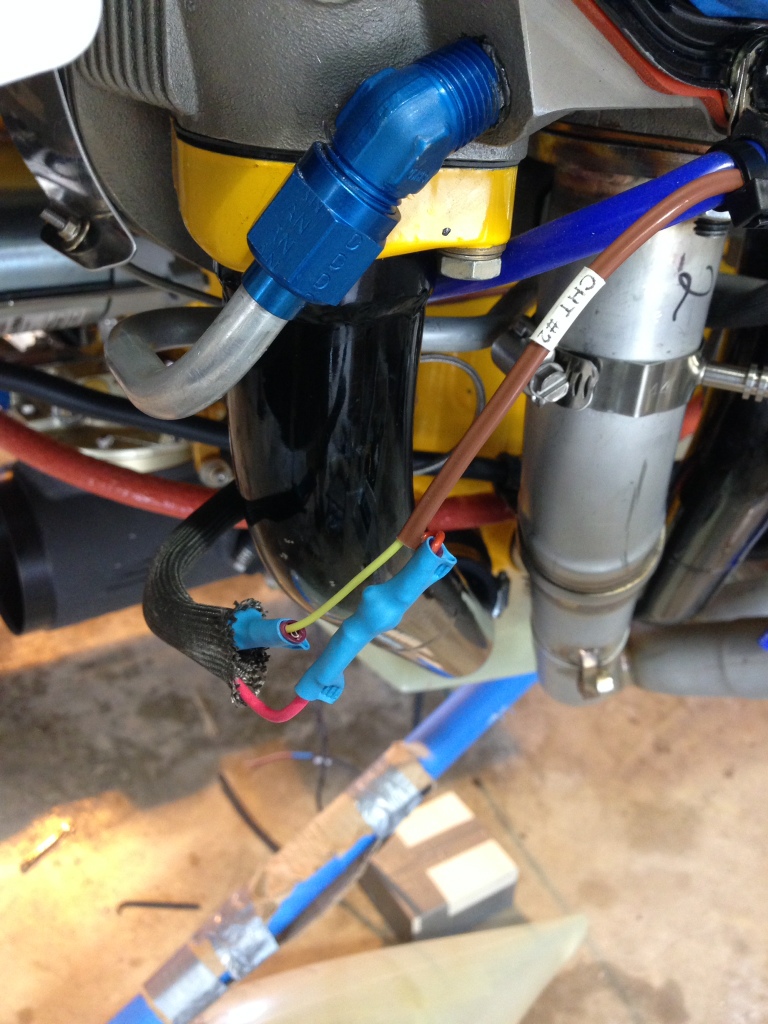
CHT, EGT, other various items
April 29, 2014 – 09:11
April 20, 2014, 10 hours
I terminated the CHT and EGT sensor wires to the sensors installed on the engine using the supplied fasteners for the loop terminals and the shield wire coverings. I decided to shrink wrap each connection point since it appeared to me that after some time inflight the protective shielding wire covers were likely going to allow the terminals to contact the various surrounding metal surfaces outside the covering.
After the EGT and CHT wire had been terminated I cleaned up the install by routing all the wires and securing them to the spark plug wire runs thus cleaning up the install.
I worked with the fuel bypass line passing through the upper air baffling above cylinder #5 and slipped a round plastic grommet around and through the baffling. I then used red RTV to help seal the hole.
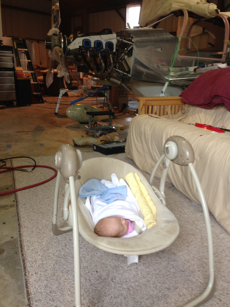
Brooklyn decide to come help daddy build today……her first day on the job… and you can guess who was in total control of the situation. 🙂
I connected the left front air vent using the Stein eyeball vent, using the supplied scat tubing.
Engine control cables, brackets
April 29, 2014 – 09:00
April 25th, 2014, 12 hours
I focused on the throttle, mixture and prop control brackets. Most of the time was spent figuring out how I wanted to route the cables and where the brackets needed to be placed. Of the three cables supplied by Vans only one was long enough for use on the Prop gov control. This was the 72.5″ version. I returned the other shorter cables to Vans and purchased the 60″ and 67″ versions.
The prop gov was to use a longer control arm but with the required direction of motion and lack of room because of the AC Compressor the travel on quadrant will be limited. It will travel about 2/3 the distance it should when cycling the prop. The prop gov itself can fully cycle the full rotational distance as required. I drilled the attach point of the cable to the quadrant lower than originally designed for. This allowed for greater travel on the prop control knob in the quadrant.
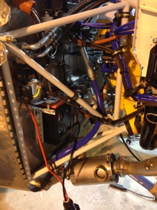
More Engine Adel Clamp action
April 21, 2014 – 07:58
April 19th, 2014. 20 Hours
My Dad and I continued working on the engine area with more Adel clamps being added to the mix. My dad started to focus on the bottom cylinder shroud and baffle rods. These are made from stainless steel and had to be cut, bent and threaded to accept the retaining nuts. Not a fun job but my dad got it done. Took him most the day to work on those rods.
I started working on the cabin tunnel and various items needing to be finalized. I mounted the TWC Battery to the inside of the firewall. I then focussed on the heater hose routing through the tunnel. I added two clamps to hold the scat tubing to the left and right tunnel wall as to route the tube away from the control rods of the rudder pedals. I then focused on routing it through the area where the fuel valve was. I originaly was to reduce the scat tube to a 3/4″ tube and then convert back to the standard size but decided against it since the scat tube can be reformed easly through the narrow space by the fuel valve. I added a cushion below the tube on the front spar to keep the tube from wearing a hole in it.
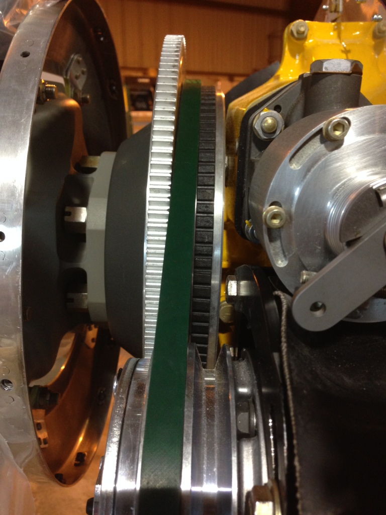
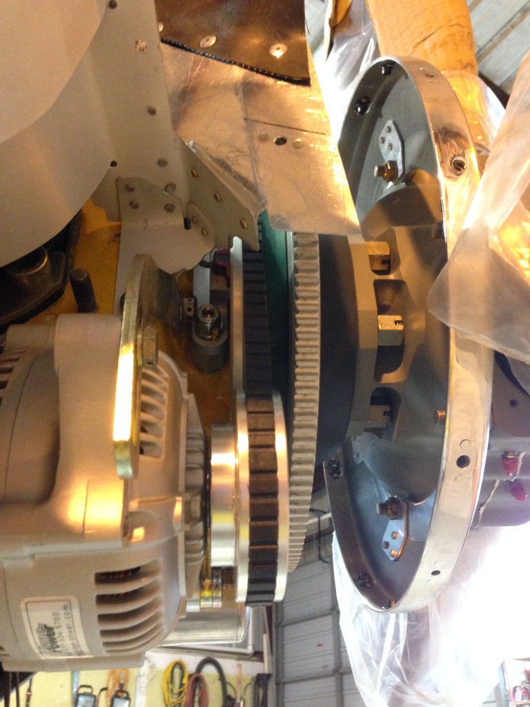
At the end of the day we had decided to mount the prop once again and tighten the AC compressor and Alternator. We did this with mininal issues but will need to retighten the Alternator belt prior to first flight.