Engine Section 46, Engine Mount and Landing Gear

Engine Cold Air Sump Modification to Engine Frame Mount

Feb 8th 2014. 3 hours

Wally Wostal (my mothers cousin) came over to weld in the modified lower cross member for the engine mount. He mad a quick job of it and was done in about 1 hour just for the welding portion. It turned out great and I later painted it with epoxy primer.

20140310-110501.jpg

20140310-110519.jpg

20140310-110535.jpg

20140310-110552.jpg

20140310-110612.jpg

Section 44, Wing Attachment

Wings First Fit

Jan 11th, 2014. 10 hours

Wings attached to fuselage using drift pins.

Heli coils placed in nose gear wheel brace. Added longer bolts for better usage with tow bar.

Hard points attached for MotoPod. Pos trimming accomplished to allow pod to contour bottom of fuselage.

20140310-105109.jpg

20140310-105133.jpg

20140310-105202.jpg

20140310-105227.jpg

20140310-105247.jpg

20140310-105316.jpg

20140310-105338.jpg

Engine

BPA Engine Arrives !!!!

Jan 17th, 2014. 1 hour.

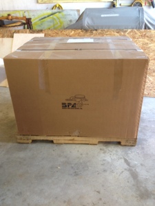
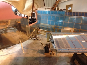
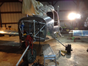
The engine arrived nicely packaged in a large box surrounded by foam. It took a while to get it out of the box since my engine hoist would not fit around the base of the box and crate. I had to cut the foam out from around the bottom of the engine to get the hoist under it all.

After working with Robert at EFII and Allen/Rhonda at Barrett Precision Engine we decided to send the engine down to me since running the engine with the EFII system and the Dyno setup would have not proven anything different from when Barrett first ran the engine with the EFII system. The engine was ready from Barrett on Nov 27th. After many communications between all parties involved the conclusion to why there where some difficulties with the first engine run was because of how the engine is operated on the dyno versus what the EFII ignition system was expecting during normal operations.

My understanding to the situation was the engine run in on the dyno locks the engine in under a high load so the engine can reach temperature quickly for proper ring break in. During this operation the MP is somewhere below 24″ most of this time causing the timing curve to not be retarded by 4 degrees to more of the normal mag timing. The engine was run at 30 degrees timing and at under a high load it caused the engine to have a pre ignition event on the number 1 cylinder likely because this cylinder might have been slightly leaner than the others. Normal operation would have kept the engine at a “squared” operation and would load the engine differently. The solution to running the EFII system on the dyno is to either disconnect the MP sensor to the ECUs causing the ECUs to run at standard mag timing to to load a “dyno map software” load.

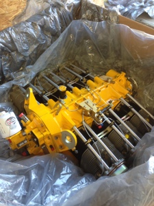
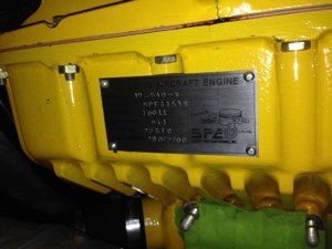
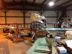
The engine was painted yellow by Barrett and we let them pick the actaul shade, we just asked for “yellow”. What color we got we really liked.

Medium Chrome Yellow
Omni MAE (Acrylic Enamel) (PPG)
Brand code: 80502
It is originally a Chrysler color and the OEM code is DT2279

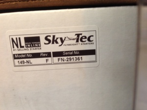
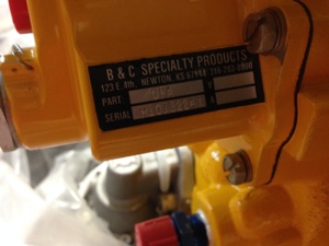
I recievd in the box,
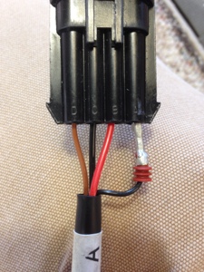
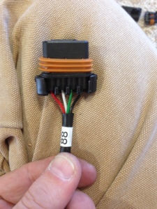
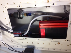
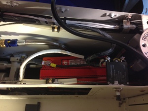
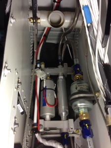
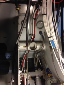
EFII complete system
Ring Gear
Starter (SkyTec 149-NL, Ser No FN-291361)
Cold Air Induction and FM300

20140120-092749.jpg

20140120-092757.jpg

20140120-092819.jpg

20140120-092842.jpg

20140310-104104.jpg

20140310-104129.jpg

EFII Engine

EFII ECU mounting

Jan 19th, 2013. 8 hours.

I punched two holes through the firewall and installed the pass through connections for a tight seal around the wires. I punched one hole for the routing of the GPS/XM antennas that will be mounted on a shelf. The other hole was for the EFII wiring harness. I didn’t like the large outer shielding for the EFII harness nor did I like the mounting pass through to be used in the firewall. I trimmed off those pieces and routed the wires through the sealable firewall pass through I mounted on the far top copilot side.

I mounted the both ECU boxes under the copilot side of the dash. They are on the firewall just forward of the brake pedals. The brake pedals in all of their possibly movement are 1.5 inches away from the boxes. I had heavy aluminum angle down there for backing the forward firewall mounted battery so I used this as the attachment point. Although not as easy as I would have hope to have access too the location still works well so far. By the way those ECU boxes could survive a bomb blast I think. They likely could have the bottom portion of the box machined a little more to take off some of the weight of the boxes.

20140120-094615.jpg

20140120-094628.jpg

20140120-094634.jpg

20140120-094622.jpg

20140120-094641.jpg

20140120-094651.jpg

20140120-094658.jpg

Avionics Wire Routing

Tunnel Battery and Center Arm Rest Audio connections

Jan 17-18th, 2013. 16 Hours

I terminated the center arm rest audio panel phone/mic connections along with the USB power point and 12V power point connections. I then moved to the center tunnel battery. Ran a 4 AWG ground wire from the battery to the firewall common grounding point.

20140120-093312.jpg

20140120-093318.jpg

20140120-093324.jpg

20140120-093330.jpg

20140120-093335.jpg

20140120-093346.jpg

20140120-093406.jpg

Avionics Wire Routing

Wing Root wire connections

Jan 11th, 2013. 16 hours
I worked the wing root wire connections on both wings and both sides of the fuselage. I also routed wires as required from the wing into the fuselage and back out as needed. This was a long process. Also terminated the coax VHF antenna’s for a male connection at the fuselage and terminated both end of the vhf cable in the wing. I decided to split the Roll servo harness at the wing root, this allowed me to route the wire through the wing and connect the servo. I needed to do this since I could not properly operate the Garmin system since it requires the CAN buss to communicate with all devices on the buss unless you have a terminator for the buss. I figured it would be easier to add the root connection than to worry about the CAN buss termination point. This also allowed me to roll the wing very near the fuselage and connect the roll servo so I could properly power the Garmin system and upgrade the system software.

I did not add a connector for the Dynon or Garmin magnetometer at this point.

20140120-083907.jpg

20140120-083927.jpg

20140120-083934.jpg

Avionics

Avionics partial Power ON

Jan 7th, 2014, 3 hours.

I walked out to the hangar with my laptop in hand and thought to myself this was very similar to the 787 where as the laptop (MX Laptop) is a very integral part of the aircraft. Thinking to myself that I have to load software to the RV10 for it to know who it is was all to similar to the 787!

I worked on getting power turned on and a partial system check out today. I flipped the Master Contractor (Batt1) and the VPX came to life along with the G3X MFD. The VPX has a basic configuration from the factory with everything turned off by the connected MFD. I did have the laptop plugged into the VPX Pro so I could upload the VPX Planner configuration that would make the system match my actual wiring. This went as expected and worked very well.

I had most all the avionics boxes unplugged for initial power on and I will slowly add boxes. I did end up with the PFD and MFD connected so that I could get the larger display screen for the VPX items on the MFD. The AOA, CO, O2 systems had power. For some reason the O2 system would shut itself off if I didn’t tell it to turn on with in 5 seconds of initial power on. I will read the manual again and see what I am missing.

The dimmable lighting of the switches was operational also. A testing of all the switches connected to the VPX was accomplished without issues.

20140108-075307.jpg

20140108-075314.jpg

MotoPod

Received the MotoPod

Monday 6th, 2014. I received the MotoPod from David Shelton. Great craftsmanship on the mod manufacturing. I ordered the pod without paint and it comes not fully assembled. I thought i might come more complete but I have to install the winch system and them final trim the upper portion of the fiberglass to mate it to the bottom of the RV10. The instruction look fairly straight forward and well thought out similar to how it was when installing the hard point in the fuselage. I honestly didn’t remember the pd being as large as it is but gosh I know have boat in case I need to go fishing! It looks to be a great addition to the RV10 and will only be taking a 9 knot hit on speed and a 45 lb hit on weight. Overall for the utility that it brings to the RV10 I can except those without a problem. I am not building a rocket ship so speed isn’t my major concern. I look forward to installing it very soon.

20140108-073327.jpg

Avionics Wire Routing

Avionics wire work

Jan 4-5, 2014. 16 hours.

I terminated control wires to the starter and contractor coils on the firewall. I connected the starter sense wire with a 1k ohm 1 watt resistor back to the VPX Pro box so it can sense when the starter is engaged. I cut to length and terminated many of the wing root connections on the left and right side. I still need to connect the pitot heater sensor led wires on the right side.

On the wings I finished terminating the right side wing wire connections and did not get to the left wing connection yet. I did not terminate the vhf RG-400 cable at the wing roots on the fuselage nor the wings yet.

I attached the VOR antenna to the vertical stabilizer tip. I ran the associated cable form the VS to the GTN 750 NAV connection. Sadly I did this twice since I ran RG-400 cable first and then realized this wasn’t the proper cable and that I had received a cable with the VOR antenna that I should be using. That made for TWO miserable trips into the tail cone that day.

Installed the firewall battery for the first time.

Uncategorized

First fly in visitor to our new home

Saturday Jan 4th, 2014 we had our first fly in visitor to arrive. Dean Conner a good friend and co worker flew his recently purchased Piper Turbo Arrow in for a visit. The conditions that day were not the best but he did a great job at landing and takeoff with the gusty crosswind that day.

Casey wanted to climb inside the airplane and NOT leave it. I started to cry when Dean was leaving and Casey really wanted to go for a flight. Honestly I did too but the condition just did not lend itself to joy rides around the pattern so I never asked.

20140108-065730.jpg

20140108-065738.jpg