System page includes Avionics. Electrical Wiring and Lighting
Category Archives: Systems
Flight Line Air Conditioning Systems
Flightline AC Evaporator to Overhead transition work
February 19, 2013 – 07:13
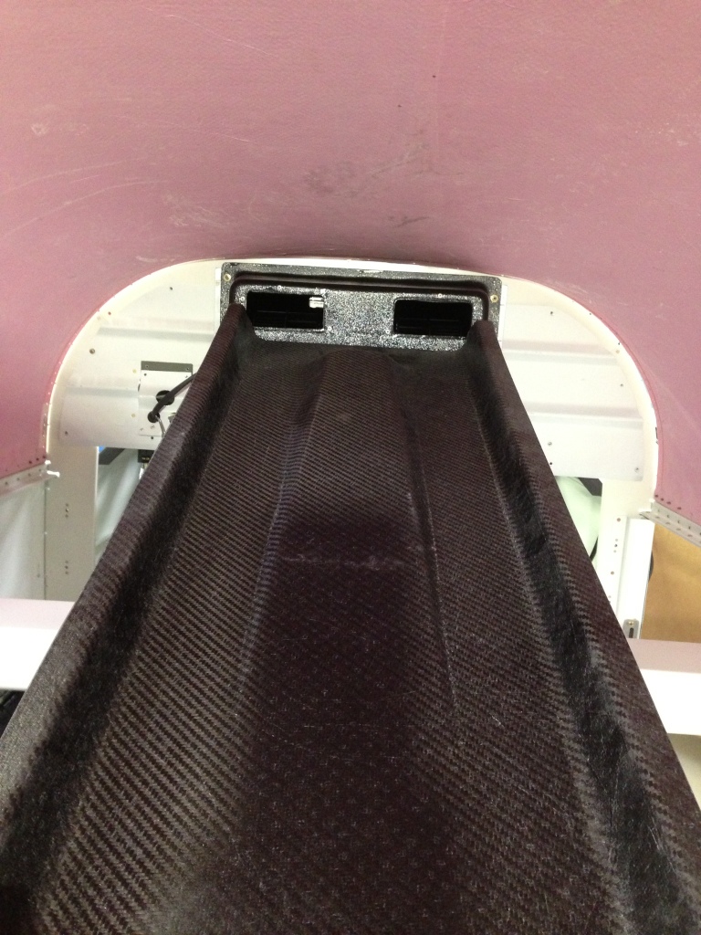
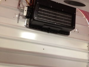
Monday Feb 18th, 2013 (2 hours) the overhead from Geoff Combs – Aerosport Products arrived and I quickly jumped into looking at what it was going to take for the evaporator and overhead to be joined. Not an easy project by no means since the evaporator isnt designed with this type if install in mind. The evaporator is originally designed for use in the Lancair airplanes mounted on the interior bulkhead. All other RV10’s have the evaporator installed aft of the baggage bulkhead on the AC tray. Although this does make for a very good looking package with it being mounted on the AC tray, less than good efficiency was coming from the system this way.
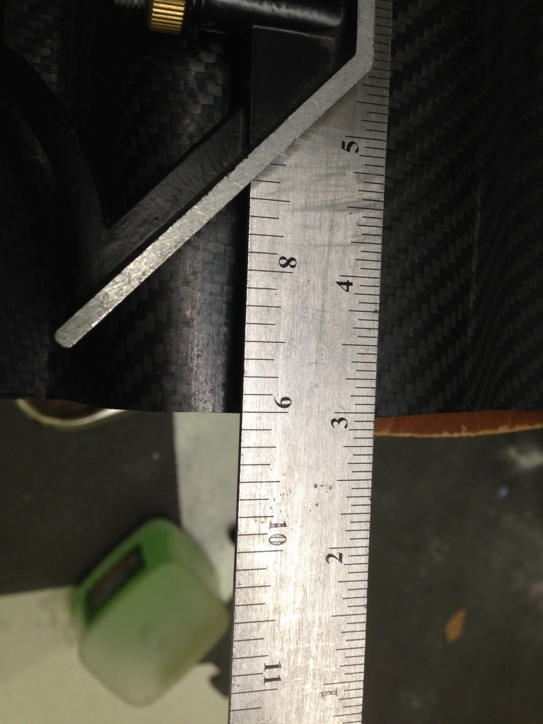
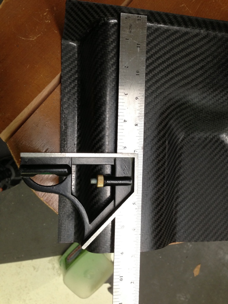
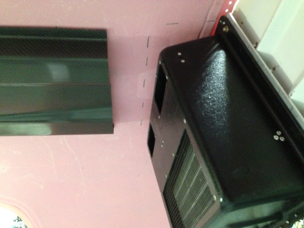
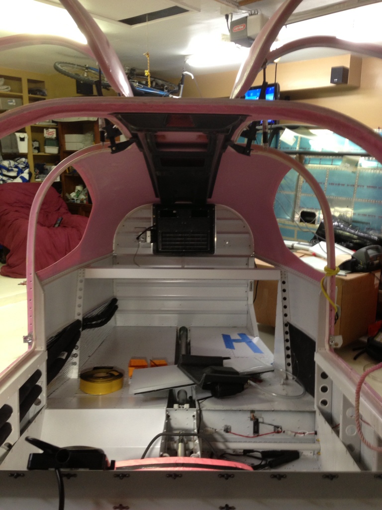
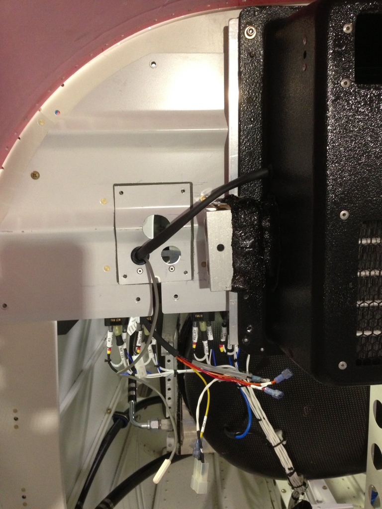
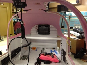
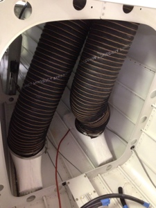
Now back to the task at hand, I decided the best way to approach making a transition form the evaporator to the overhead was to trim out the differnce from the overhead the amount that the evaporator sticks out from the baulkhead. This came to about 6 inches and I decided to add three more inches thinking this might be far enough in front of the evaoprtor to make the inlet air ramps fit. I will need to trim out more as it turns out. I then fitted the overhead to the cabin top and lets just say that Geoff did a fantastic job on the overhead, fits very well. I am in the process of making a shroud that can act as a back plate that will wrap around the evaporator front face and sides. I will then match the shroud to the cabin top and cut out the two air exhaust holes that match to the evaporator. I am hoping this will act as the “back wall” to the tranisiton.
Fuel Pump, Tunnel Battery Relay wiring
February 18, 2013 – 08:20
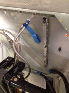
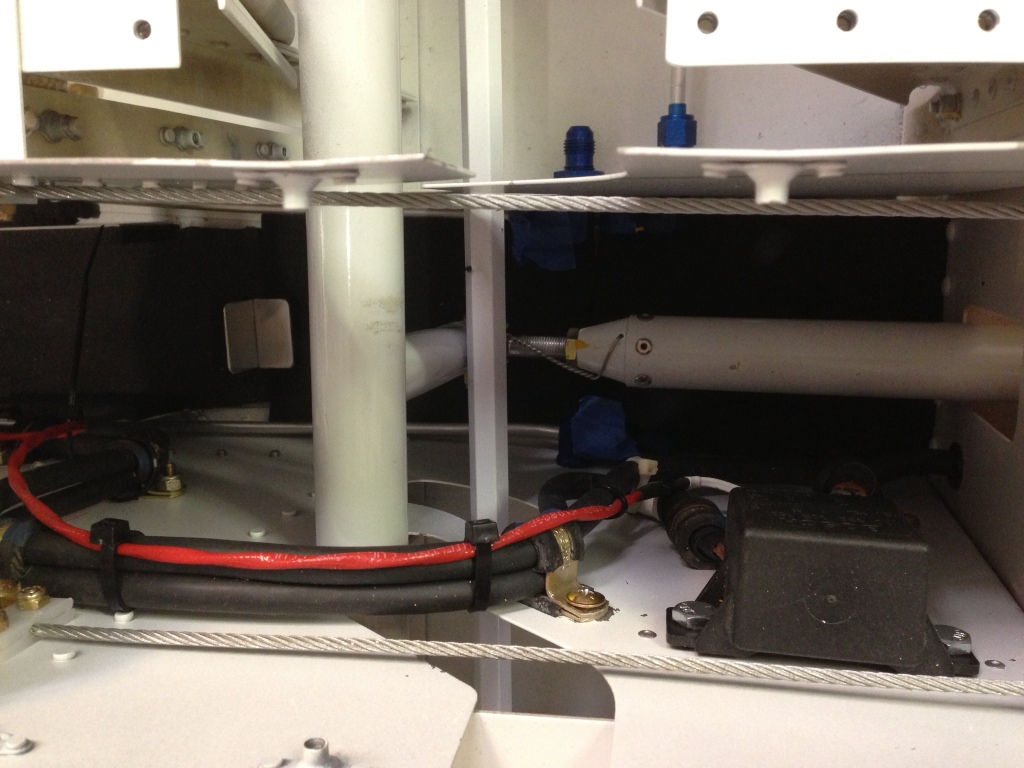
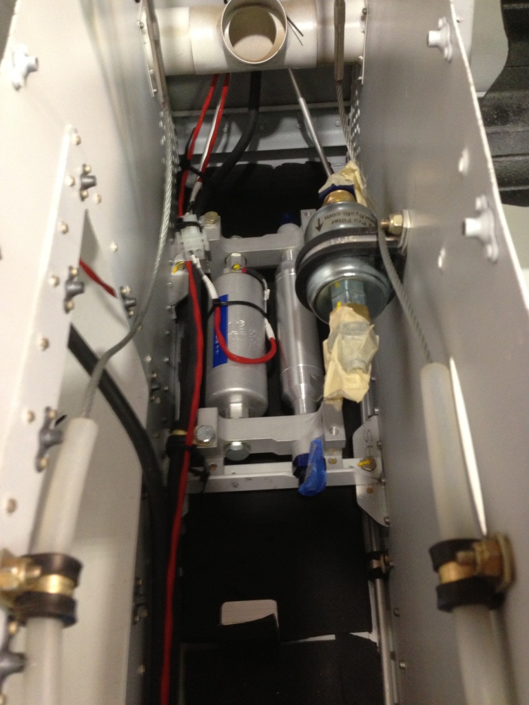
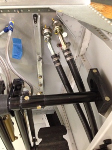
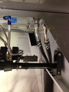
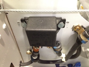
Feb 17th, 2013 (9 Hours). I spent the day wiring the Fuel Pump and Tunnel Battery relay contractor. Process was simple but time consuming, working in the tunnel is tight and the routing of the wire is very critical along with securing the wires. I wired up to cables one for the relay that included a diode, this cable is routed up to the general area of where I think the Tunnel Battery switch will be located with some “extra” cable since I don’t have the exact location determined.
The Fuel Pump wire route deals with similar issue as did the Tunnel Battery relay. I created a connector that is 5 inches long, connects to the terminals on the fuel pump on one end and then has a connector for easier removal and install if the need is required (I hope not). The cable is the routed up to the VPX Pro future location with some extra length added on.
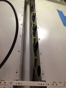
I wrapped the high pressure and low pressure AC lines in insulation to help keep them more efficient and keep them from having water vapor condensing on them thus getting it all on the inside of the aircrafts walls, etc.
Flightline AC system tray, flap sensor, and flap motor wiring
February 18, 2013 – 08:04
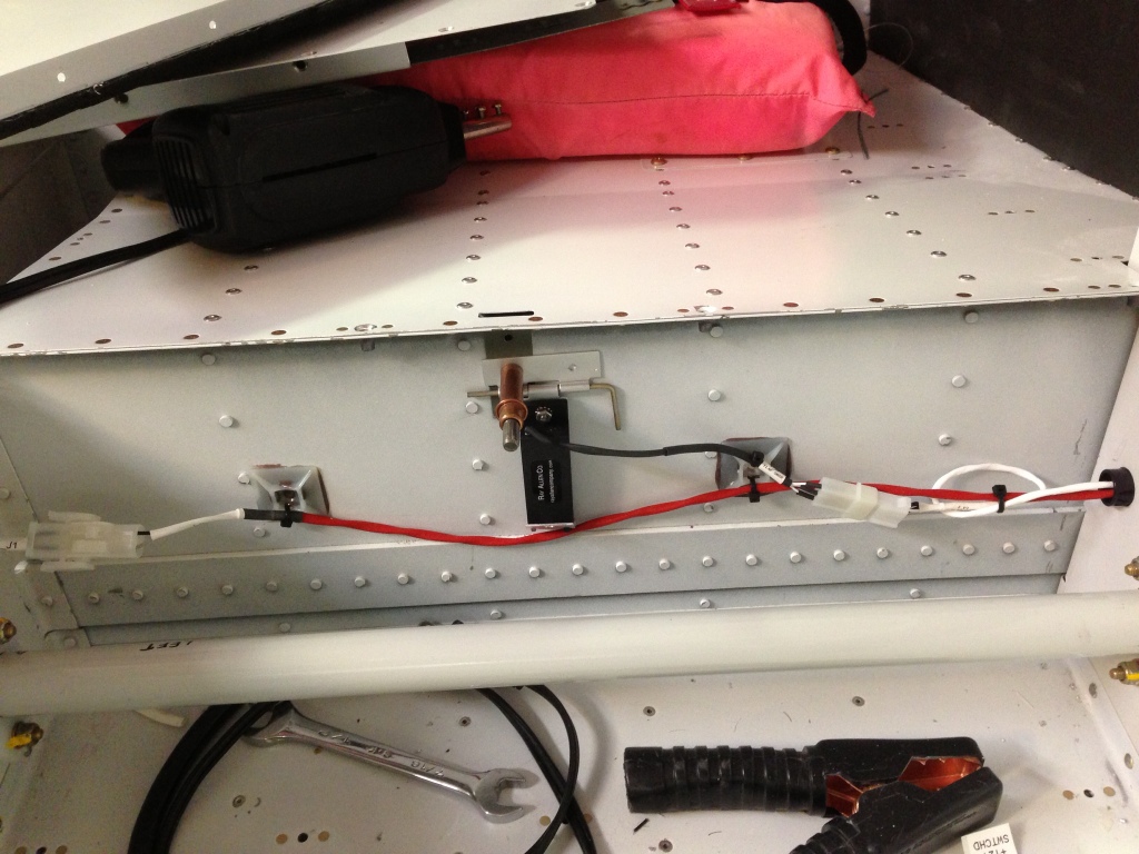
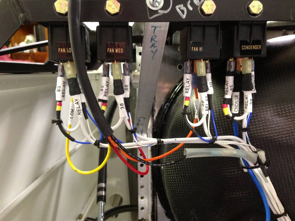
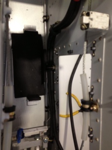
Feb 16th, 2013 (8 hours). Started the day with wiring all the electrical components on the Flightline AC system tray located behind the aft baggage bulkhead. I had already wired the condenser relay so I was only concentrating on the evaporator fan 3 relays and the switch located on the dryer. I needed to pull new wire from the front of the fuselage to the system tray and this took longer than expected since my little helper (Casey) had tugged on one of the “fish tape” lines I had previously ran thru the conduit under the aft baggage area. Once I got back on track with the wire pulls I was able to pull 4- 2 conductor cables as needed for the AC controls.
I wired the three relays, low, med, and high fan connections to the control lines from the CB-1 controller that will be mounted in the panel up front. I then ran the power wires from the aft circuit breaker board located just below the AC tray up to the relays. I wired in diodes across all the relays since the relays only have an internal resistance and not a diode. The wiring diagram shows they have internal diodes but looking at the data sheet for the specific relays I was shipped shows otherwise.
The dryer located on the aft section of the AC tray has a “sensor switch” that helps keep the system safe in operational parameters by sensing the low and high pressure of the system. I don’t know the technical term for it so I will just call it a switch for now. This sensor switch is connected to the circuit breaker board below the tray and fused at 5 amps, it then passes thru the sensor and makes its way back to the front of the AC to be connected to the relay that will control the compressor. Relay Pin 85 will have the sensor connected to to it, Pin 86 will be connected to CB-1 Pin 2.
A sensor (thermister) is placed just in front of the evaporator for sensing the return air, this sensor allows the CB-1 to try and maintain a set temperature. It will control the compressor as needed off/on to allow for the system to become more efficient.
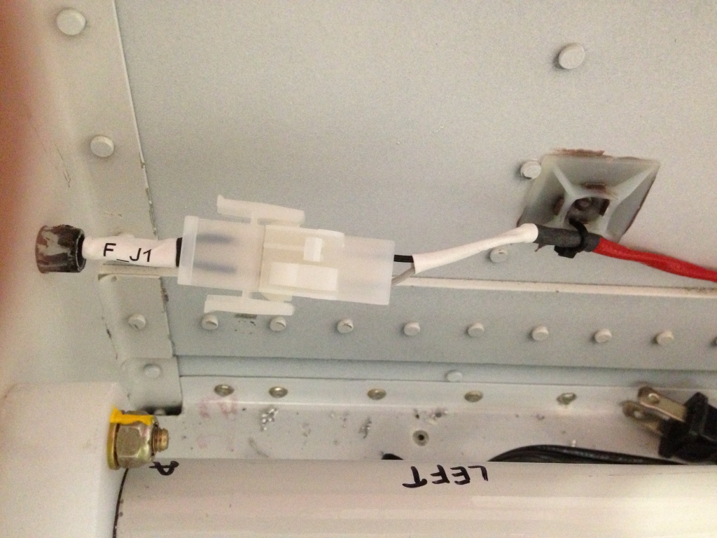
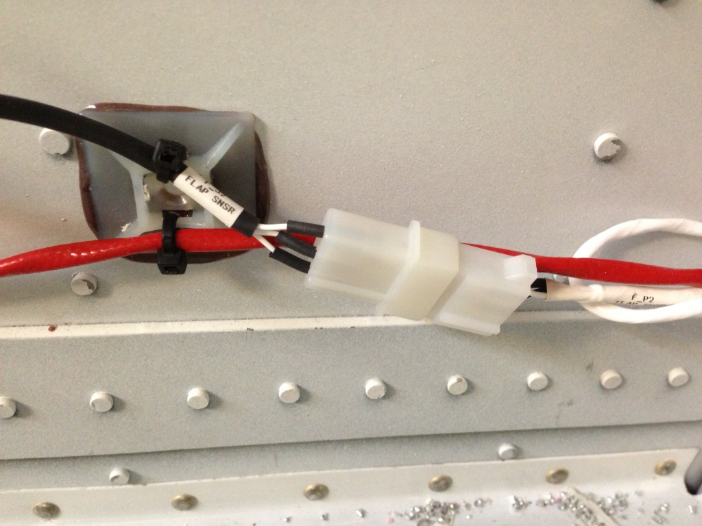
I finished the AC wiring and moved to the flap motor and flap position sensor wiring. I ran 1- 2 conductor and 1- 3 conductor cables from the flap sensor and flap motor locations up to where the Vertical Power (VPX-Pro) future location. Simple process but time consuming.
Flightline AC, Access panel pass thru for hose and wire evaporator connections.
February 18, 2013 – 07:19
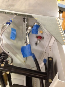
Friday 15th, 2013 (4 hours), I worked on cutting the pass thru holes for the high and low pressure evaporator lines plus the fan electrical wires and thermister sensor. I initial made the two holes for the pressure lines and then added the pass thru for the wires once I figured out where the pressure lines needed to be. Simple process and was done rather quickly. I then concentrated on the hose routing in the tray area. I cut and crimped all the connection points required aft of the baggage bulkhead wall and finalized the routing of the hoses. I will add more pictures to this posting later, not all taken at this point.

Flightline AC System, Evaporator install
February 11, 2013 – 13:48
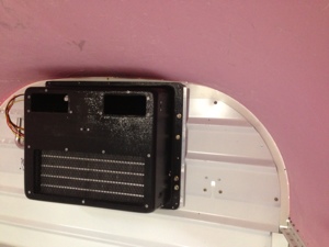
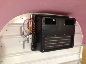
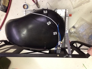
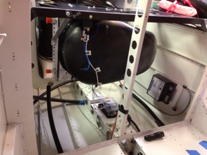
Feb 10, 2013, (2.5 hours) Worked on figuring out how to install the Flighline AC Evaporator. I essentially centered the evaporator up high on the baggage bulkhead wall. I then used some of the predrilled holes on the left side of the evaporator and matched drilled those into the bulkhead wall. On the left side there where no pre-drilled holes so added my own. I added nut plates on the back side of the baggage walls. I still need to create a small around the low and high pressure lines of the evaporator panel that can be removed and add a port thru the baggage wall out to the condensor cooling air outlet.
Flightline AC System
February 8, 2013 – 09:18
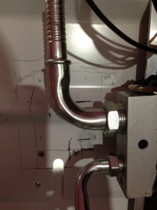
Feb 2-3, 2013 (8 hours) I worked with installing the Flightline AC system firewall pass thru. I finally decided on the best location for the pass thru that was different from most all other RV10 installations based upon my location of the firewall battery, master contact relay, and future battery pass thru. I drilled the thru holes and then applied Bio-therm and attached the pass thru to firewall. I then installed the battery pas thru located very near the same locations since I had all the required tools in hand. I then installed the two different size hose on the aft size of the firewall. I once again used a different configuration than most other installations because of the pass thru locations. I used two 45* hose attachments on the aft side and two 90* hose attachments forward of the firewall. I installed the crimp clamp on the aft side of the firewall and re-situated the hose that run aft to the AC unit.
I received the evaporator core that will be mounted on the inside of the baggage bulkhead. This “again” is not done as others have done before since the idea is to help move the weight more forward and also to place the intake of the evaporator directly into the “conditioned air” environment. There had been reports of other installs that were not able to keep the system tightly sealed and thus caused poor performance of the AC system. This different install will certainly create new install challenges but I think overall this will work well. I will need to trim the Aerosport overhead so the evaporator will slide up into it for better alignment. A shroud duct will need to be made to cover and join together the area. Further updates to come.
Aft 12Volt Aux Battery Power and associated Terminal/Fuse Block
January 28, 2013 – 09:51
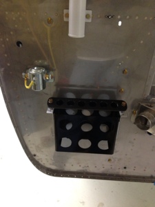
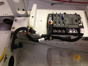
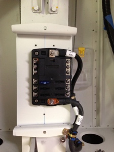
This weekend (Jan 27, 2013) I spent 9 hours working on various aspects of installing the remaining aft section of the 4 AWG wire coming from the Tunnel AUX Battery. I started by installing a Blue Sea ST Blade Fuse Blocks (Overton’s p/n: 71230) that includes a negative bus and positive bus. Max amperage is 100 Amps the block can handle. Max amperage is 30 Amps per circuit.
Before I could mount the block where I finally decided to mount it, I had to remove my previously modified battery box location that was modified to hold two batteries since I did not need the extra weight back there. I drilled out the rivets holding the double battery mount to remove it. Once I did this, I had clear access to where I wanted to mount the fuse block.
I mounted the fuse block and then terminated the 4 AWG switched wire coming from the Tunnel AUX bus and terminated a 4 AWG ground wire to the block. I then moved onto creating a support bracket to hold the wires and conduit exiting the aft baggage deck.
Flight Line Air Conditioning Condenser Fit/Temp Install
January 28, 2013 – 09:12
This weekend (Jan 26, 2013) I decided to work on the Flight Line Air Conditioning Condenser and associated wiring. I spent several hours attaching the condenser to the mounting tray (only took a couple of minutes) and then spent most my time on the electrical connection from the condenser fan to the Relay and then down to the power source. I epoxied some wire attach point to the carbon fiber plenum to help with wire management. I mounted the relay to the tray since the wires from the power wire from the condenser fan can connect directly to the rely without being lengthened. I then routed the ground wire from the condenser and power wire from the relay to the power block below both of them.
I worked on routing the control wire from the Flight Line AC controller thru the fuselage from Front to aft. I have yet to terminate any of these wires since placement of the evaporator is not known yet. I am still awaiting my shipment of the evaporator and hope to receive it this week so I can start work installing it.
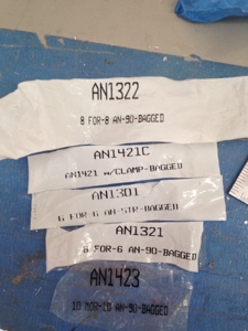
I spent many hours trying to figure out the proper location for the AC low and high pressure hose thru the firewall. This is frustrating since every location seems to have interference since I mounted a firewall battery and contractor up there. To add frustration, I don’t have the proper oriented hose fitting I would like to use for the install. The bag sent includes a bunch of angled fitting but I have no technical data to substantiate where they go. I will contact Flight Line and see what I can figure out.
Total hours spent 10 hours.
Tunnel Battery Relay Contact and 4 AWG wire routing Forward and Aft
January 23, 2013 – 10:39
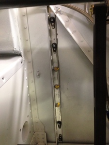
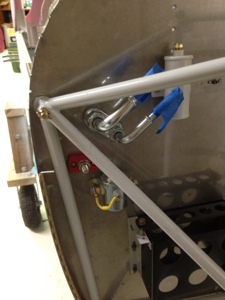
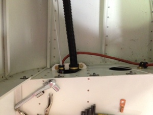
Jan 13, 2013, I spent (8 hours) much of my time drilling various holes to mount cable tie brackets and Adel clamps. I started with drilling mounting holes throughout the aft tunnel where the control tubes are located. I secured the 4 AWG wire on the port side of the aircraft to the vertical side walls every couple of inches so the wire would not interfere with the control cables.
I then focused my attention to the center tunnel where the contact relay is located and begin to terminate the 4 AWG wire to the proper ring terminals and placed heat shrink tubing around the wire to add rigidity and protection from electrical contact with other items near by. After working with how I would route the 4 AWG wire forward towards the firewall I then continued to drill holes to mount Adel clamps for holding the wire run.
The wire run in the mid tunnel is verified to not interfere with the flight controls. everything is clamped with Adel clamps and clearance is maintained throughout the flight control area.
A 20 amp circuit breaker is mounted in the same general area of the contact relay to provide protection for the power wire for one of the Plasma Electronic Ignitions. The power source comes directly from the battery to the fuse then up to a switch that can select either the Tunnel or Firewall battery as a power source. Then the wire connects to a 7.5 Amp circuit breaker and then an Ignition switch and then onto the Ignition module. />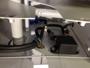
Firewall Battery mount and support
January 23, 2013 – 10:16
Jan 19, 2013 I worked on adding a firewall mounted battery box (9 Hours). Vans sales a firewall battery mount kit for the PC680 battery so I decided to buy it. It was interesting reading the plans for the battery box versus the plans for the RV10, very different! After drilling many holes in the battery box to decrease the weight being added I moved to creating a support structure for the firewall. I used to angle aluminum pieces with various mounting holes and nut plates to attach the battery box and to attach the support structure to the firewall. I again drilled lightning holes in the angle aluminum to decrease the weight but maintain structural integrity. I then used bio-therm so seal the holes thru the firewall.