Category Archives: Finish Kit

Engine Prop ShowPlanes Cowling

ShowPlanes Cowling Work

March 17th to 23rd, 120 hours

My dad and I mostly worked on the baffles and cowling top and lower halves. What a surprise this was to me since I had thought this was going to be much easier than it is.

My dad started working on the MotoPod, exchanging two plates that were incorrectly supplied to us. He placed the cable covers on and lubed the cables just prior to closing it all up. He then moved on to pulling off all the blue protective tape on the wings that had been there since we received the parts.

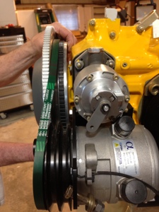
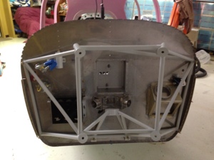
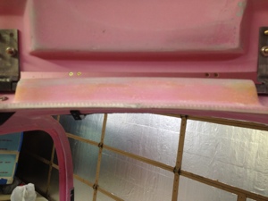
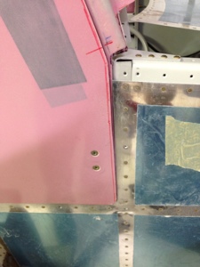
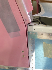
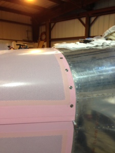
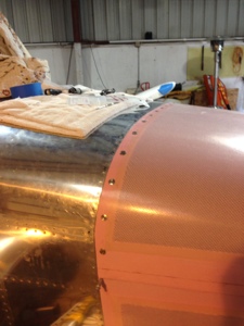
We then both started working on the top and bottom cowl halves since it was easer to work using two people. I had purchased SkyBolts for the top firewall half and drilled the final mounting holes in the cowling. Sadly I realized after it was to late that I had not properly positioned the cowling so I had to fiberglass the holes back full and start over again. The Show Planes cowl is a great product and easy to work with and is easy customizable. It was required that I grind off several places where the Skybolts back plates mount so they would set properly. While I was working on cutting the cowling my dad started installing the Plane Power Alternator, 70 AMP. He then moved over to installing the AC Compressor. He looped the drive belts around the ring gear and alternator but could not get them around the AC Compressor. It was later realized the AC Compressor that we had (Alpha I believe) had a larger pulley on it than what is currently shipping from FlightLine AC. Flightline promptly shipped a new compressor out to me. Sadly we could not mount the compressor so we could further work on the left side of the cowling air inlet ramps.

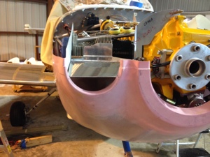
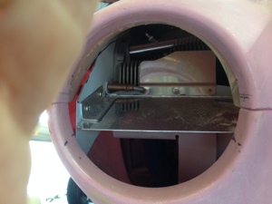
I started concentrating on the right side air inlet ramps. With the ShowPlanes cowl there is a special inlet scoop that comes from the left and right side down to the engine fuel servo. I though the right side would be easy….. well not really… but I am figuring out how it should have been thus making it much easier than how I was going about fitting it all. I figured it out how I wanted to make the inlet ramp for cooling air and engine induction air should be the only issue was how to hold all the movable parts together long enough to get an idea how it wants to be all attached. With everything in place and the bottom cowl on it makes for a rather tight fit. The instructions call for about 1/8″ clearance for engine movement. This seemed a little small so I increased the space and thus am having to rework fiberglass.

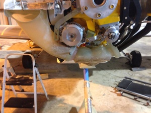
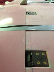
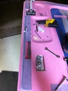
Meanwhile my dad was attaching the baffle rubber material as we had a good lower and upper cowl fitment and repeatability for mounting it all. The bottom cowl was attached using the hinge method on the side with one screw fastener on each bottom firewall point. The tope cowl got the Skybolts as mentioned above. And the lower inner portion that wraps around the landing gear had the pressure recovery mold attached to the airplane bottom with clecos and screw fasteners. This all created a good secure cowl for finishing the air inlet ramps.

Overall we had a good work week but we certainly have much more to get done before we are finished with the cowl and baffles.
20140325-143942.jpg

20140325-144000.jpg

20140325-144015.jpg

20140325-144029.jpg

20140325-144044.jpg

20140325-144054.jpg

20140325-144105.jpg

Engine Section 46, Engine Mount and Landing Gear

Engine Cold Air Sump Modification to Engine Frame Mount

Feb 8th 2014. 3 hours

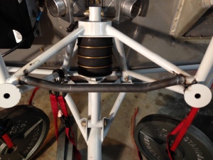
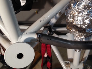
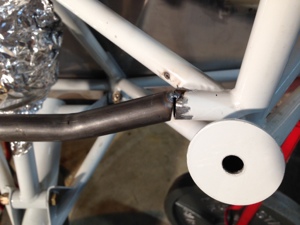
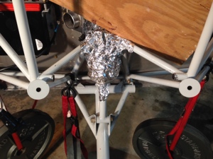
Wally Wostal (my mothers cousin) came over to weld in the modified lower cross member for the engine mount. He mad a quick job of it and was done in about 1 hour just for the welding portion. It turned out great and I later painted it with epoxy primer.

20140310-110501.jpg

20140310-110519.jpg

20140310-110535.jpg

20140310-110552.jpg

20140310-110612.jpg

Section 46, Engine Mount and Landing Gear

Landing Gear mount

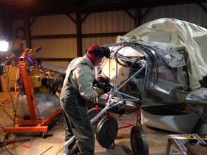
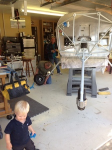
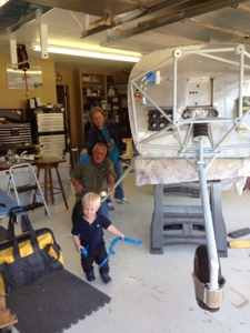
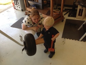
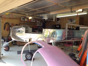
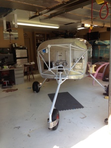
March 16th, 2 hours. I decided to set the fuselage on the gear since i would need to be moving the “airplane” in the near future. More on that story later on. My parents had come into town so I had extra help and asked my father to lend a helping hand. This process went very smoothly and honestly had I known it was that easy I would have waited a bit longer. Being on the gear makes it a little more difficult to work on especially for a short guy like myself, 5’4″ !!

20130417-082041.jpg

20130417-082111.jpg

20130417-082133.jpg

20130417-082149.jpg

20130417-082208.jpg

20130417-082221.jpg

Finish Kit Section 46, Engine Mount and Landing Gear

Section 46, Engine Mount

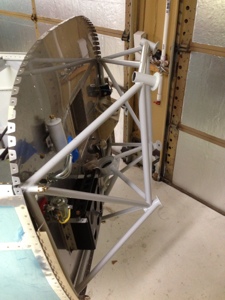
Feb 2nd, 2013 I reinstalled the engine mount for the last time (4 hours). I read Section 46 for installing the engine and I will have to say the instructions are horrible. I drilled and mounted the engine mount using one hole. I then continued to the next hole only to find the hole alignment was off by half a hole. After further investigation all the holes were off by a lot. The plans tell you to align the engine mount to the other holes and use the engine mount as a drill jig to finish enlarging the original prepunched holes in the firewall. Well had I done that the engine would likely be mounted half a hole off to the right side. I used the engine mount as a drill jig and continued to drill the holes one by one with no other bolts installed in any of the engine mounting locations to the proper 3/8″ size. After doing this I held the engine mount in place and as expected the engine mount holes were off. I decided (wished I would had done this prior) to look on the chat groups to find the mounting engine discussion. From what I gathered, the engine mont behaved as most all others did and that folks essential worked with the bottom 4 holes first. The two bottom most inner holes align the best so the suggestion was to bolt one of these holes and then re drill the adjacent hole. This allowed the engine mount to be center. Working my way to the lower side holes I was able to re drill those holes with only a slight enlarging of the firewall side of the hole with the aft side of the firewall hole still perfectly in shape. After finishing this I moved to the top engine mount holes. These put up a little mor fight but I was able to lightly persuaded them into place and then re-drilled them as needed. All bolts and hardware installed and torqued to specs.
20130208-083850.jpg

20130208-083859.jpg

Finish Kit Section 45, Cabin Doors and Transparencies

Section 45, Door Fitting – Seal, plus tunnel access cover

December 27-28th, I continued to work on fitting the McMaster door seal to the door openings. I cut a piece of the seal and put epoxy mixture inside of it and pushed it into place. I allowed this to cure and then continued with the remaining portion of the doors after pulling the seal off and cleaning up the rough excess epoxy. This method allowed a nice holding edge to be formed for the seal so hopefully it won’t slip off later.

I also worked on the tunnel and added the access panel to the left side. I have decided to put one of the PC680 batteries in the tunnel since the air conditioning unit is behind the luggage bulk head. It has been discussed before about the CG issues of the RV10. With weight of the AC unit and the oxygen equipment in the back. It is highly likely I will encounter a CG issue before I reach gross weight so the batteries need to be moved forward. If it is determined that a battery needs to be moved aft, the original battery location is reserved for exactly this type of scenario. Either way we should be able to cover the CG issue once the aircraft is totally built out. There will be a PC680 mounted on the firewall also.

Consideration needs to be given to the fact that the correct choice of prop needs to be made to help control the total weight and CG requirements. Either the Hartzel or MT 3 bladed prop will be my choice.

Spent 7 hours working mostly all the above mentioned work.

20130110-141900.jpg

20130110-141908.jpg

20130110-143440.jpg

20130110-143452.jpg

Finish Kit Section 45, Cabin Doors and Transparencies

Section 45, Door fitting, door seal, door strut

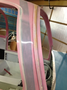
December 9th I started the day but sanding the inner door seal to the proper height for the McMaster Carr door seal to fit properly. Various sanding techniques were required to lower the inner ridge of the door opening. This took about 6 hours.

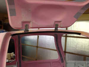
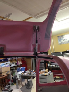
Mounted the hydraulic door struts to both doors. I had to modify the Bansbach strut attachment point to be slightly more narrow to attach to the PlaneAround cabin top strut bracket that is made for the after market door seal. 5 hours.

Drilled the PlaneAround center door locking block into the fuselage. This is the center latch thta helps pull in the center of the door. This is the after market latch mechanism solution for the SB that Vans Issued. I had to modify the center blocks to lower their height so the shaft would clear them. 2 hours.

20121228-195307.jpg

20121228-195326.jpg

20121228-195351.jpg

20121228-195921.jpg

Finish Kit Section 45, Cabin Doors and Transparencies

Section 45, Door Fitting to Cabin Top

December 8th. Spent about another 10 hours working to fit the doors to the cabin top. Much guess work seemed to be needed to get the proper fit of the door into cabin top opening. Lots of sanding then fitting, then sanding.

20121228-194014.jpg

20121228-194035.jpg

20121228-194051.jpg

20121228-194126.jpg

20121228-194135.jpg

Finish Kit Section 45, Cabin Doors and Transparencies

Section 45, Door Mechanism continued

Sill more work required on the doors. Spent 4 hours working the mechanism on the right door. I’m getting it very near where I want it and hopefully a couple more hours I will have it completed.

20121204-204102.jpg

Finish Kit Section 45, Cabin Doors and Transparencies

Section 45, Door Locking Mechanism

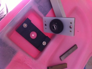
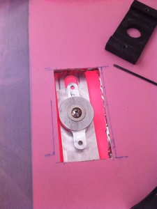
December 2nd, I started working on the exterior door key lock for for the IFlyRv10 flush door handles. I did not buy by the manufacture flush door key set so I went to the local aviation store and picked up two identically keyed door lock sets to retro fit into the doors. With a little modifying I was able to make the locks function as required to lock the handle from being opened. I then epoxied the right door flush handle and center door gear box spacers into place. 6 hours worked.20121203-074423.jpg
20121203-074109.jpg

Finish Kit Section 45, Cabin Doors and Transparencies

Section 45, Cabin Doors and Transparencies

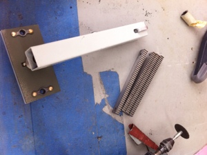
Dec 1st, 2012, I started the left and right exterior flush mount handle, interior door handle mechanism, door locks, and PlaneAround center door latch. It took a while to verify the door cutouts and to understand exactly what I was supposed to be doing. Essentially I was combining three different products at one time that need to function as one unit without any larger amount of friction. With various measurements, marks, and cuts the fitting began with fairly good results. I first used the metal template for the IFlyRV10 Flush mount door handles. The metal template was perfect for making a very nice cutout in the exterior door panel. I then moved to Vans plans of making the internal door handle and locking mechanism. The flush door handle kit requires the interior vans handle mechanism to be modified by shortening the main shaft and inner shaft to accommodate the push button that is located in the center of the two shafts but exposed on the exterior of the door. I cut the gear racks as required by the plans and fit those into the door handle interior door pocket. I then moved to fitting the center door latch by PlaneAround. Made the cut out and fitted the gear box. I was able to get the left and right doors to the same finished state but wasn’t able to epoxy in the items needing to be affixed to the door yet. I called it a day after 12 hours.

20121203-073334.jpg

20121203-073343.jpg

20121203-073354.jpg