Category Archives: Electrical

Electrical Systems

Overhead Switch, Air Vents, and Light install

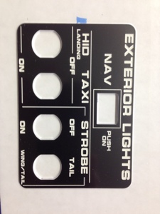
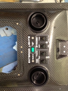
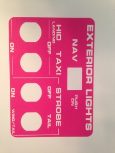
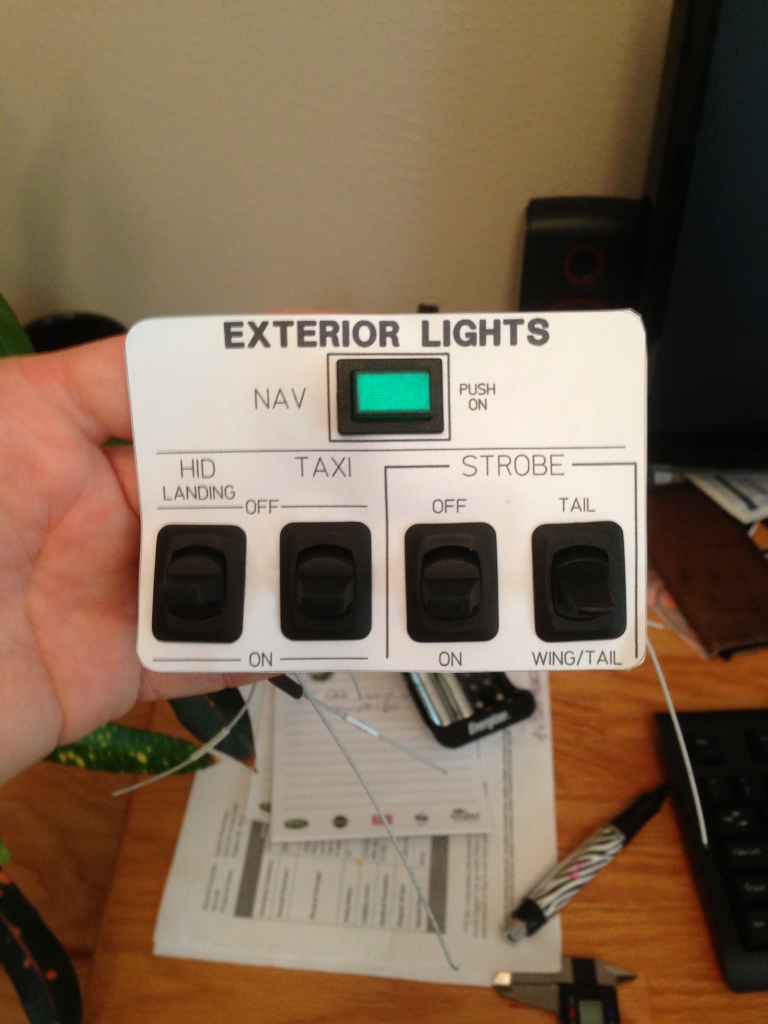
March 9th, 2013 (9 hours for all). Received the overhead switch panel from Panel Express and install the switches to see how it would look. I had to cut out a portion of the overhead to accommodate the switches to be removed with the panel. I had originally thought that I would mount the switches into the thru holes capturing the overhead panel and the switch panel. I quickly realized that would be way to hard to accomplish with little to no hand room. (Total time for this work and prior, 4 hours)

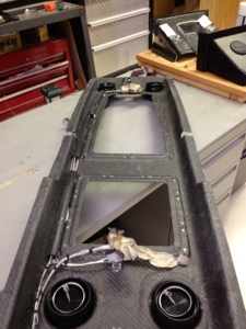
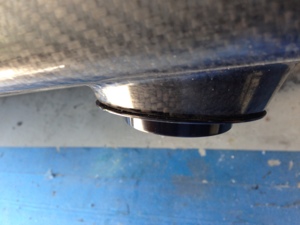
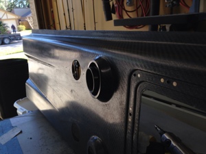
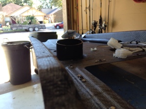
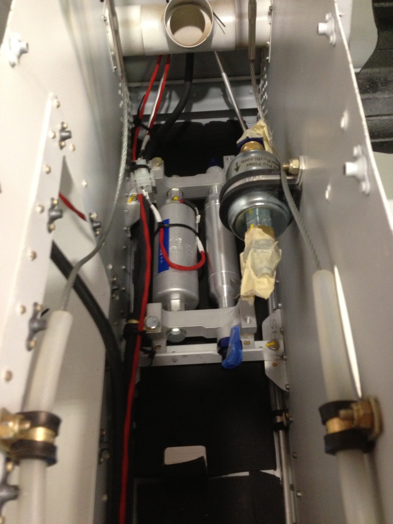
I then moved to installing the overhead air vents that John sent me from Flightline AC. He searched long and hard trying to find the appropriate vents that can accommodate the large amounts of air the evaporator can flow. The air vents are very nice and are low profile so not to protrude into head space. The only issue is they might be a little more difficult to adjust since they are low profile but I think they will work perfectly over all. I did need to trim the retainer ring down a couple of inches since it was to tall to fit between the cabin top and the overhead. I used a very small amount of grease on the retaining plastic nut that holes the body of the air vent so to create more drag on the nut and hopefully keep it from loosing on it own. Since these vents are larger than the standard air vents the overhead was designed for I had to take the hole diameter out to the very edges of the mounting face. Using the air grinder with a round sanding drum helped in the process of fitting the vents. (3 hours)

Moving on to the led lights, we installed four of the Aveo Eyebeam Touch lights into the overhead. I had already drilled out the holes to accommodate them in a prior step so I installed them and connected the internal wiring of the overhead to the lights. (2 hours)

At some point later in the build process when the interior starts to become complete I will install strip LED lighting to the outside edge of the overhead. This will provide the cabin with lighting and will be dimmable.

20130415-100733.jpg20130415-100810.jpg20130415-100902.jpg20130415-100923.jpg20130415-100937.jpg20130415-100952.jpg

Electrical Systems

Overhead Switch Panel design

March 3rd, 2013 I continued working on the overhead panel. I will be mounting the Landing, Taxi, Strobe, Nav, and strobe wing/tail select switches in the overhead. I installed the front seats and overhead to verify the switches are accessible. While the switch labeling wont necessary be in front of you for easy viewing it will be easy to read and will be come muscle memory once you remember where the switches are and the order they are in.

I am using Front Panel Express to create and build the panel in. It will be black with white lettering. For some reason my printer decided to printout the scale panel in a shade of pink. Sure my wife would like that. I cut out the holes in the panel t verify switch placement and spacing. once everything was satisfactory to my likening I order the panel. Worked about 8 hours.

20130305-143949.jpg

20130305-143940.jpg

Electrical Systems

Overhead light and wire work

March 2nd 2013 I spent the day working with the overhead attaching a couple of wire run conduits and wire tie down points. I epoxied all of those in place and then started to run the wires that would be installed in the overhead. Four Aveoflash led lights will be installed, two aft overhead the passengers and the other two will be over the front seats. I cut the mounting hole for the two rear lights but did not cut the front two holes since they will be mounted in the front aluminum panel that attaches to the overhead. I am waiting on a circle cutter from Aircraft Spruce.

I terminated the four wires that will be connected to the Aveaoflash led lights and ran two extra wires with connectors for the overhead led stripes that will mounted along the outside of the overhead once the interior gets installed. worked about 6 hours.

20130305-143205.jpg

Electrical Systems

Fuel Pump, Tunnel Battery Relay wiring

Feb 17th, 2013 (9 Hours). I spent the day wiring the Fuel Pump and Tunnel Battery relay contractor. Process was simple but time consuming, working in the tunnel is tight and the routing of the wire is very critical along with securing the wires. I wired up to cables one for the relay that included a diode, this cable is routed up to the general area of where I think the Tunnel Battery switch will be located with some “extra” cable since I don’t have the exact location determined.
The Fuel Pump wire route deals with similar issue as did the Tunnel Battery relay. I created a connector that is 5 inches long, connects to the terminals on the fuel pump on one end and then has a connector for easier removal and install if the need is required (I hope not). The cable is the routed up to the VPX Pro future location with some extra length added on.
I wrapped the high pressure and low pressure AC lines in insulation to help keep them more efficient and keep them from having water vapor condensing on them thus getting it all on the inside of the aircrafts walls, etc.

20130218-081921.jpg

20130218-081931.jpg

20130218-081939.jpg

20130218-081952.jpg

20130218-081959.jpg

Electrical Flight Line Air Conditioning Systems

Flightline AC system tray, flap sensor, and flap motor wiring

Feb 16th, 2013 (8 hours). Started the day with wiring all the electrical components on the Flightline AC system tray located behind the aft baggage bulkhead. I had already wired the condenser relay so I was only concentrating on the evaporator fan 3 relays and the switch located on the dryer. I needed to pull new wire from the front of the fuselage to the system tray and this took longer than expected since my little helper (Casey) had tugged on one of the “fish tape” lines I had previously ran thru the conduit under the aft baggage area. Once I got back on track with the wire pulls I was able to pull 4- 2 conductor cables as needed for the AC controls.
I wired the three relays, low, med, and high fan connections to the control lines from the CB-1 controller that will be mounted in the panel up front. I then ran the power wires from the aft circuit breaker board located just below the AC tray up to the relays. I wired in diodes across all the relays since the relays only have an internal resistance and not a diode. The wiring diagram shows they have internal diodes but looking at the data sheet for the specific relays I was shipped shows otherwise.
The dryer located on the aft section of the AC tray has a “sensor switch” that helps keep the system safe in operational parameters by sensing the low and high pressure of the system. I don’t know the technical term for it so I will just call it a switch for now. This sensor switch is connected to the circuit breaker board below the tray and fused at 5 amps, it then passes thru the sensor and makes its way back to the front of the AC to be connected to the relay that will control the compressor. Relay Pin 85 will have the sensor connected to to it, Pin 86 will be connected to CB-1 Pin 2.
A sensor (thermister) is placed just in front of the evaporator for sensing the return air, this sensor allows the CB-1 to try and maintain a set temperature. It will control the compressor as needed off/on to allow for the system to become more efficient.
I finished the AC wiring and moved to the flap motor and flap position sensor wiring. I ran 1- 2 conductor and 1- 3 conductor cables from the flap sensor and flap motor locations up to where the Vertical Power (VPX-Pro) future location. Simple process but time consuming.

20130218-080334.jpg

Electrical Systems

Aft 12Volt Aux Battery Power and associated Terminal/Fuse Block

This weekend (Jan 27, 2013) I spent 9 hours working on various aspects of installing the remaining aft section of the 4 AWG wire coming from the Tunnel AUX Battery. I started by installing a Blue Sea ST Blade Fuse Blocks (Overton’s p/n: 71230) that includes a negative bus and positive bus. Max amperage is 100 Amps the block can handle. Max amperage is 30 Amps per circuit.

Before I could mount the block where I finally decided to mount it, I had to remove my previously modified battery box location that was modified to hold two batteries since I did not need the extra weight back there. I drilled out the rivets holding the double battery mount to remove it. Once I did this, I had clear access to where I wanted to mount the fuse block.

I mounted the fuse block and then terminated the 4 AWG switched wire coming from the Tunnel AUX bus and terminated a 4 AWG ground wire to the block. I then moved onto creating a support bracket to hold the wires and conduit exiting the aft baggage deck.20130128-095053.jpg20130128-095107.jpg20130128-095126.jpg20130128-095135.jpg

Electrical Systems

Tunnel Battery Relay Contact and 4 AWG wire routing Forward and Aft

Jan 13, 2013, I spent (8 hours) much of my time drilling various holes to mount cable tie brackets and Adel clamps. I started with drilling mounting holes throughout the aft tunnel where the control tubes are located. I secured the 4 AWG wire on the port side of the aircraft to the vertical side walls every couple of inches so the wire would not interfere with the control cables.

I then focused my attention to the center tunnel where the contact relay is located and begin to terminate the 4 AWG wire to the proper ring terminals and placed heat shrink tubing around the wire to add rigidity and protection from electrical contact with other items near by. After working with how I would route the 4 AWG wire forward towards the firewall I then continued to drill holes to mount Adel clamps for holding the wire run.

The wire run in the mid tunnel is verified to not interfere with the flight controls. everything is clamped with Adel clamps and clearance is maintained throughout the flight control area.

A 20 amp circuit breaker is mounted in the same general area of the contact relay to provide protection for the power wire for one of the Plasma Electronic Ignitions. The power source comes directly from the battery to the fuse then up to a switch that can select either the Tunnel or Firewall battery as a power source. Then the wire connects to a 7.5 Amp circuit breaker and then an Ignition switch and then onto the Ignition module. />
20130123-102612.jpg

20130123-102619.jpg

20130123-102628.jpg

20130123-102634.jpg

Electrical Systems

Firewall Battery mount and support

Jan 19, 2013 I worked on adding a firewall mounted battery box (9 Hours). Vans sales a firewall battery mount kit for the PC680 battery so I decided to buy it. It was interesting reading the plans for the battery box versus the plans for the RV10, very different! After drilling many holes in the battery box to decrease the weight being added I moved to creating a support structure for the firewall. I used to angle aluminum pieces with various mounting holes and nut plates to attach the battery box and to attach the support structure to the firewall. I again drilled lightning holes in the angle aluminum to decrease the weight but maintain structural integrity. I then used bio-therm so seal the holes thru the firewall.

20130123-101633.jpg

20130123-101623.jpg

20130123-101640.jpg